OM-1646-001_w.pdf - 第20页
1 OM-1646 1. Scope In the dual transfer system, two lanes are used to transfer PCBs alternately , assuming that the PCB transfer tim e is "0" (zero) an d improving product ivity . Furthermore, this system can b…

OM-1646
Cont-4
Contents
Page
1005-001
16. Pneumatic and Electrical Diagrams ............................................... 41
16.1 Pneumatic and Mounting Diagrams ........................................ 41
Conveyor (Pneumatic Diagram) .................................... 41
Conveyor (Mounting Diagram) ...................................... 42
16.2
Sensor and Load Layout ......................................................... 43
Conveyor Section Layout (Outside : A-Lane) ................ 43
Conveyor Section Layout (Outside : B-Lane) ................ 44
Conveyor Section Layout (Inside : A-Lane) ................... 45
Conveyor Section Layout (Inside : B-Lane) ................... 46
16.3 Parts Location ......................................................................... 47
Conveyor Section Layout .............................................. 47
16.4 Circuit Diagram ....................................................................... 48
Conveyor M Circuit Diagram (1) .................................... 48
Conveyor M Circuit Diagram (2) .................................... 49
Conveyor M Circuit Diagram (3) .................................... 50
Conveyor M Circuit Diagram (4) .................................... 51
Conveyor M Circuit Diagram (5) .................................... 52
Conveyor M Circuit Diagram (6) .................................... 53
Conveyor M Circuit Diagram (7) .................................... 54
Conveyor M Circuit Diagram (8) .................................... 55
Conveyor M Circuit Diagram (9) .................................... 56
Conveyor M Circuit Diagram (10) .................................. 57
U08 I/O P.C.B. STLT CNVR (L) ..................................... 58
U08 I/O P.C.B. STLT CNVR (R) ..................................... 59
16.5 Cable Connection Diagram ..................................................... 60
Dual Transfer Harness Connection Diagram 1 .............. 60
Dual Transfer Harness Connection Diagram 2 .............. 61
17. Specications ................................................................................. 62
1
OM-1646
1. Scope
In the dual transfer system, two lanes are used to transfer PCBs alternately,
assuming that the PCB transfer time is "0" (zero) and improving productivity.
Furthermore, this system can be used effectively to place components
simultaneously on different PCBs (for different models), reducing the
number of PCBs in the middle of processing and making it possible to make
appropriate production whenever necessary.
The transfer specications comply with the SMEMA transfer standards.
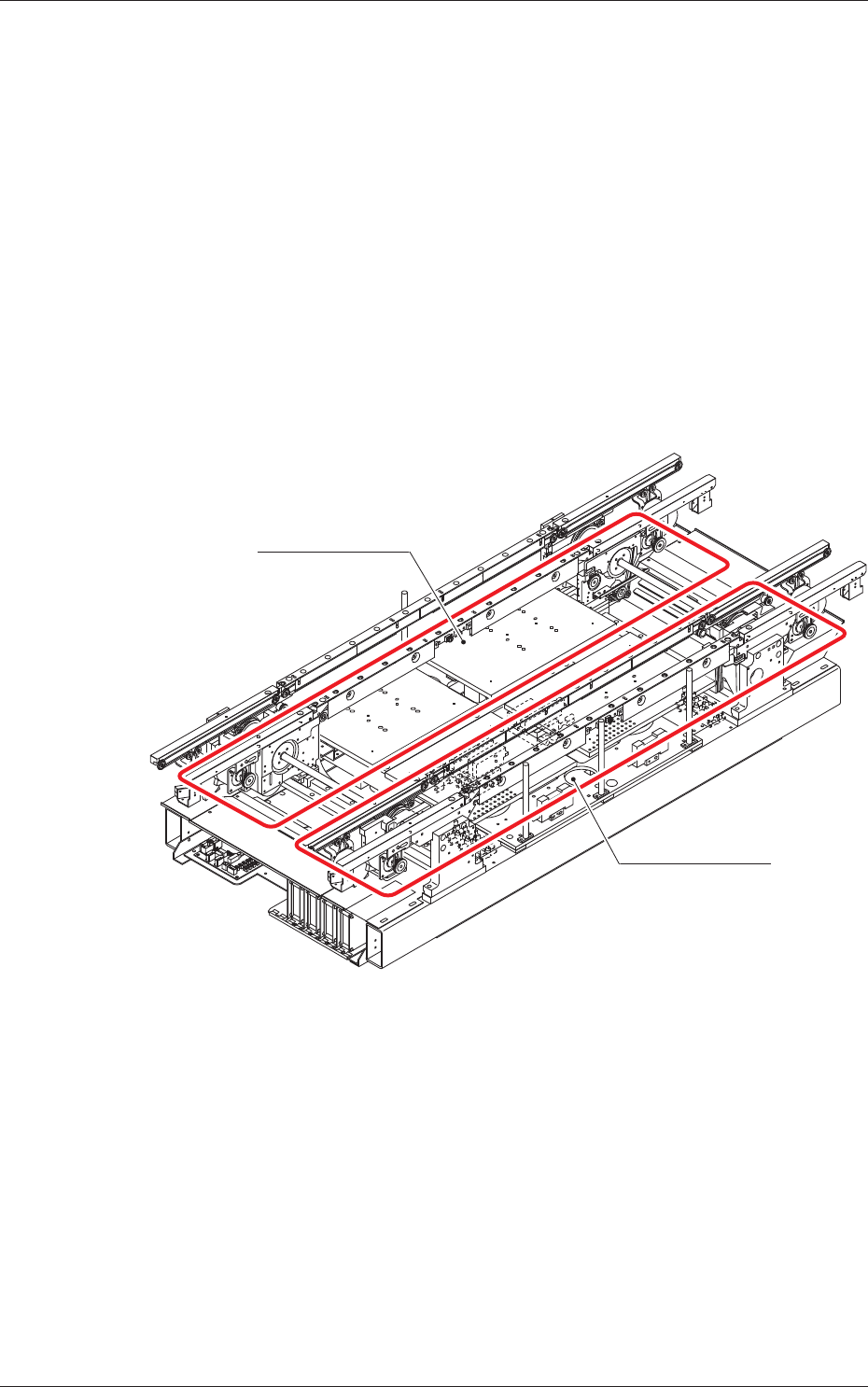
2. Rough View of Machine
Lane A
Lane B
Front Side of Machine
F1
1005-001
1. Scope
2
OM-1646
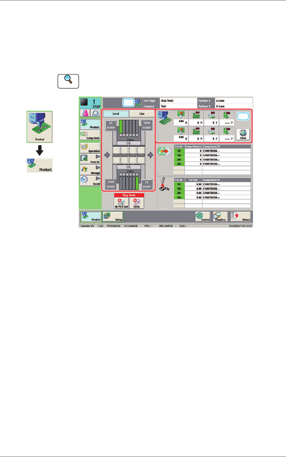
3. Automatic Operation
This window enables you to view the current operation status and production
condition such as the production model names (pattern program names), etc.,
and the information on the prospective number of nished PCBs and presumable
deterioration in the operation rate based on pickup errors, etc.
Reference
Refer to the Instruction Manual of the SIGMA-G5 for the information except for
dual transfer.
[1]
[2]
Automatic Operation F2
Graphic
Development
1005-001
3. Automatic Operation