OM-1646-001_w.pdf - 第26页
7 OM-1646 4. "PP CHANGE" Window This window enables the operator to change the pattern program. Reference Refer to the Instruction Manual of the SIGMA-G5 for the information except for dual transfer . [2] [1] […
6
OM-1646
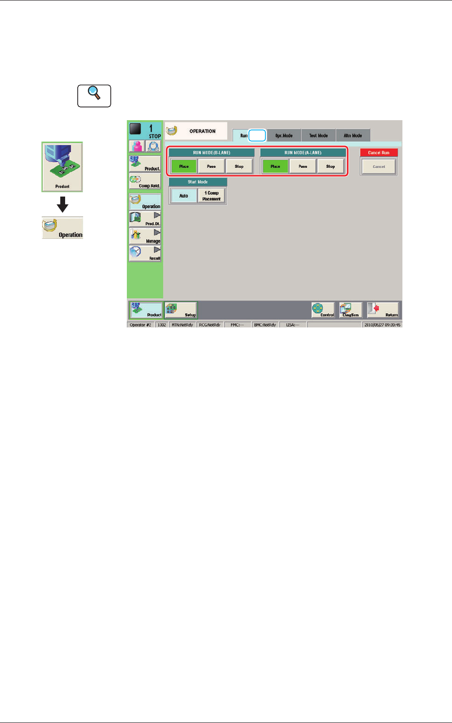
3.2 "Run Mode" Tab Sheet
This tab sheet enables the operator to designate the operation mode for each
lane.
Reference
Refer to the Instruction Manual of the SIGMA-G5 for the information
except for dual transfer.
[1]
Run Mode F6
[1] "Run Mode" Selection Buttons (A or B Lane)
Press either one of the following buttons to select the desired run mode.
[Place] Button
: Select this button to set the machine in the "PLACE
(Automatic Operation)" mode.
[Pass] Button
: Select this button to set the machine in the "PASS" mode.
In the "Status" display section on the upper area of the "Product." window, the
changed operation mode is displayed.
Graphic
Development
1005-001
3.2 "Run Mode" Tab Sheet
7
OM-1646
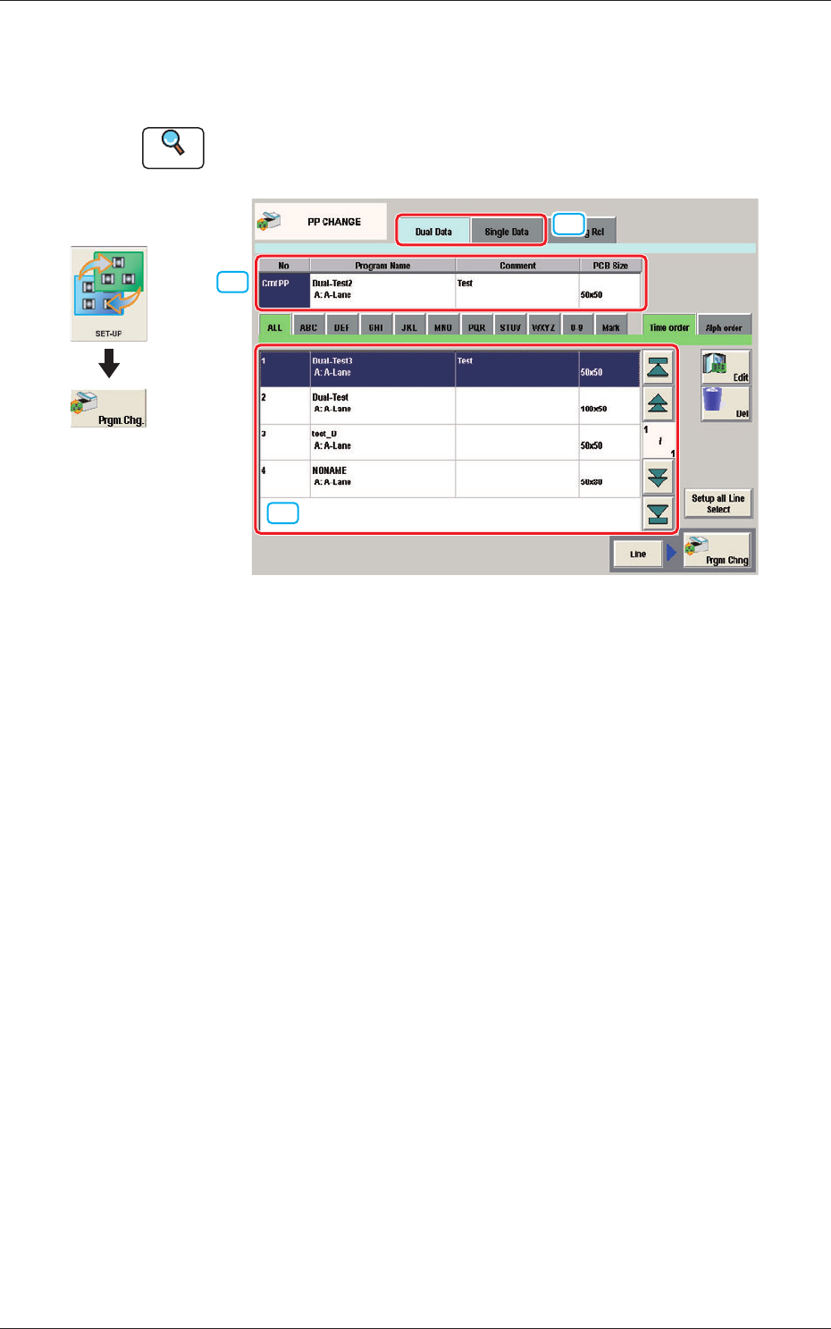
4. "PP CHANGE" Window
This window enables the operator to change the pattern program.
Reference
Refer to the Instruction Manual of the SIGMA-G5 for the information
except for dual transfer.
[2]
[1]
[3]
PP CHANGE F7
[1] Dual Data, Single Data
Dual Data
When selected, the pattern programs for dual transfer are displayed in the
"
[3] Patter Program List
"
area.
Single Data
When selected, the pattern programs for single transfer are displayed in the
"
[3] Pattern Program List
"
area.
[2] Pattern Program Select tabs
The data items displayed in "[3] Pattern Program List" are divided into the
tab sheet items and displayed.
[3] Pattern Program List
The registered pattern programs are displayed as a list.
When the pattern program has been selected in the dual transfer data, the
program name for each of the Lane A and Lane B, comment and PCB size
are displayed in this area.
Graphic
Development
1005-001
4. "PP CHANGE" Window
8
OM-1646
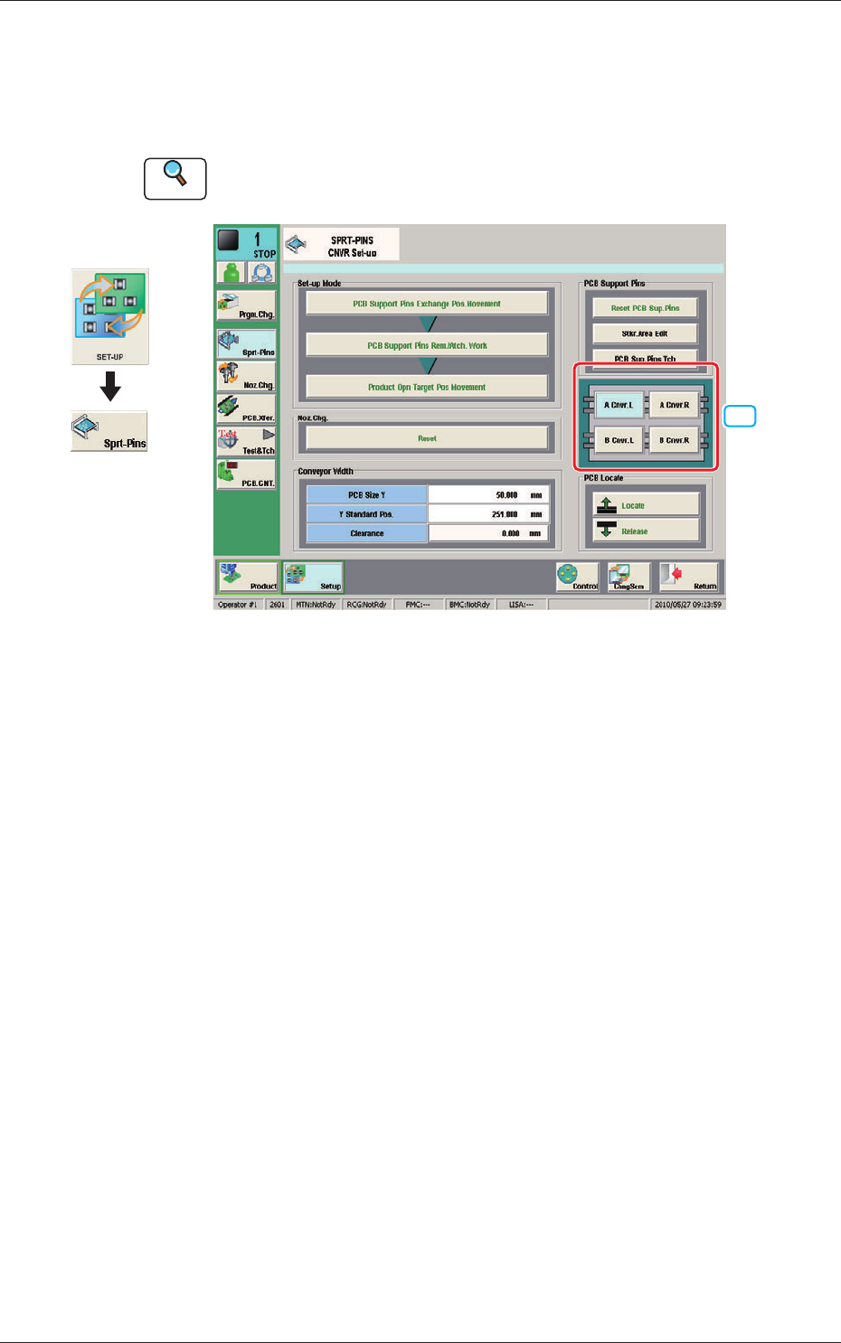
5. "SPRT-PINS" Window
This window is used when the support pin change work for each conveyor is
to be performed.
Reference
Refer to the Instruction Manual of the SIGMA-G5 for the information
except for dual transfer.
[1]
SPRT-PINS F8
[1] PCB Locate Section Select Button
Using these buttons, the PCB positioning section is selected on the side of
set-up operation for each conveyor.
[A Cnvr. L] Button
: When selected, the PCB positioning section L on the
side of the lane A is selected.
[B Cnvr. L] Button
: When selected, the PCB positioning section L on the
side of the lane B is selected.
[A Cnvr. R] Button
: When selected, the PCB positioning section R on the
side of the lane A is selected.
[B Cnvr. R] Button
: When selected, the PCB positioning section R on the
side of the lane B is selected.
Graphic
Development
1005-001
5. "SPRT-PINS" Window