OM-1646-001_w.pdf - 第27页
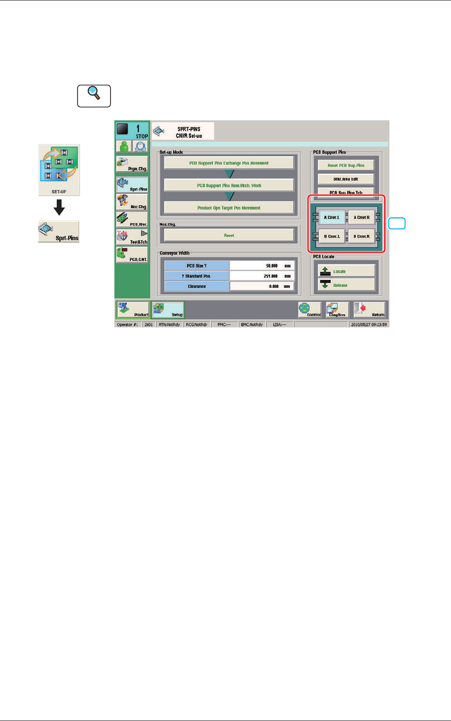
8 OM-1646 5. "SPRT -PINS" Window This window is used when the support pin change work for each conveyor is to be performed. Reference Refer to the Instruction Manual of the SIGMA-G5 for the information except f…
7
OM-1646
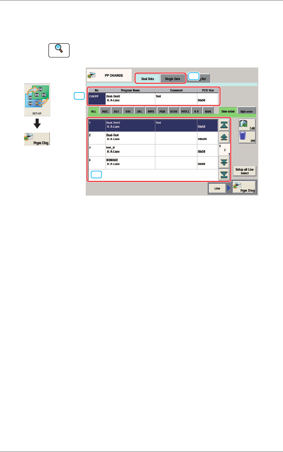
4. "PP CHANGE" Window
This window enables the operator to change the pattern program.
Reference
Refer to the Instruction Manual of the SIGMA-G5 for the information
except for dual transfer.
[2]
[1]
[3]
PP CHANGE F7
[1] Dual Data, Single Data
Dual Data
When selected, the pattern programs for dual transfer are displayed in the
"
[3] Patter Program List
"
area.
Single Data
When selected, the pattern programs for single transfer are displayed in the
"
[3] Pattern Program List
"
area.
[2] Pattern Program Select tabs
The data items displayed in "[3] Pattern Program List" are divided into the
tab sheet items and displayed.
[3] Pattern Program List
The registered pattern programs are displayed as a list.
When the pattern program has been selected in the dual transfer data, the
program name for each of the Lane A and Lane B, comment and PCB size
are displayed in this area.
Graphic
Development
1005-001
4. "PP CHANGE" Window
8
OM-1646
5. "SPRT-PINS" Window
This window is used when the support pin change work for each conveyor is
to be performed.
Reference
Refer to the Instruction Manual of the SIGMA-G5 for the information
except for dual transfer.
[1]
SPRT-PINS F8
[1] PCB Locate Section Select Button
Using these buttons, the PCB positioning section is selected on the side of
set-up operation for each conveyor.
[A Cnvr. L] Button
: When selected, the PCB positioning section L on the
side of the lane A is selected.
[B Cnvr. L] Button
: When selected, the PCB positioning section L on the
side of the lane B is selected.
[A Cnvr. R] Button
: When selected, the PCB positioning section R on the
side of the lane A is selected.
[B Cnvr. R] Button
: When selected, the PCB positioning section R on the
side of the lane B is selected.
Graphic
Development
1005-001
5. "SPRT-PINS" Window
9
OM-1646
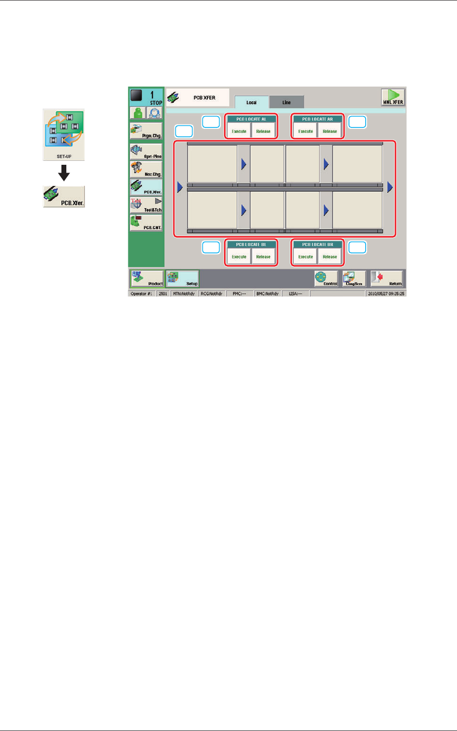
6. "PCB XFER" Window
This window enables the operator to move the PCB on each block on each
lane on the conveyor to the next block.
[1]
[2] [2]
[2] [2]
PCB XFER F9
[1] Conveyor Image Display Pane
Each block in the graphic image of the conveyor is provided with a button
function.
When the [START] button on the operation panel is pressed in 10 seconds
after a conveyor block button, the PCB is transferred to the block position.
[2] PCB LOCATE (PCB LOCATE AL,
AR, BL, BR)
Using these buttons, the PCB positioning is performed for each lane and
each block.
When the [START] button on the operation panel is pressed in 10 seconds
after the [Execute] button, the backup base of the selected stage moves up
and the PCB is positioned.
When the [START] button on the operation panel is pressed in 10 seconds
after the [Release] button, the backup base moves down and the PCB
positioning is released.
Graphic
Development
1005-001
6. "PCB XFER" Window