OM-1646-001_w.pdf - 第28页
9 OM-1646 6. "PCB XFER" Window This window enables the operator to move the PCB on each block on each lane on the conveyor to the next block. [1] [2] [2] [2] [2] PCB XFER F9 [1] Conveyor Image Display Pane Each…
8
OM-1646
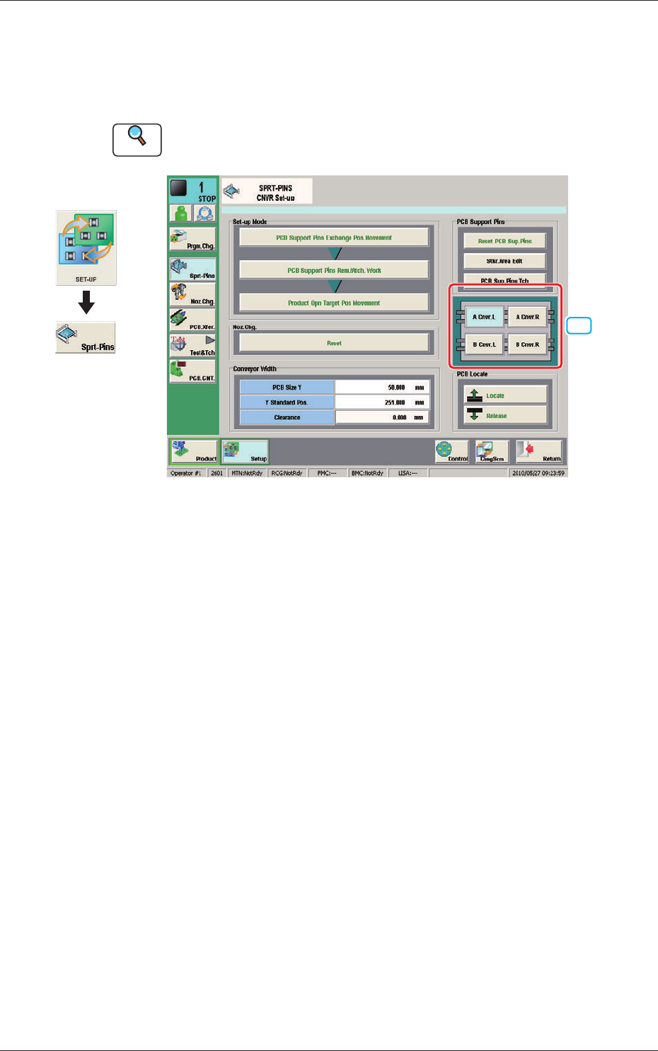
5. "SPRT-PINS" Window
This window is used when the support pin change work for each conveyor is
to be performed.
Reference
Refer to the Instruction Manual of the SIGMA-G5 for the information
except for dual transfer.
[1]
SPRT-PINS F8
[1] PCB Locate Section Select Button
Using these buttons, the PCB positioning section is selected on the side of
set-up operation for each conveyor.
[A Cnvr. L] Button
: When selected, the PCB positioning section L on the
side of the lane A is selected.
[B Cnvr. L] Button
: When selected, the PCB positioning section L on the
side of the lane B is selected.
[A Cnvr. R] Button
: When selected, the PCB positioning section R on the
side of the lane A is selected.
[B Cnvr. R] Button
: When selected, the PCB positioning section R on the
side of the lane B is selected.
Graphic
Development
1005-001
5. "SPRT-PINS" Window
9
OM-1646
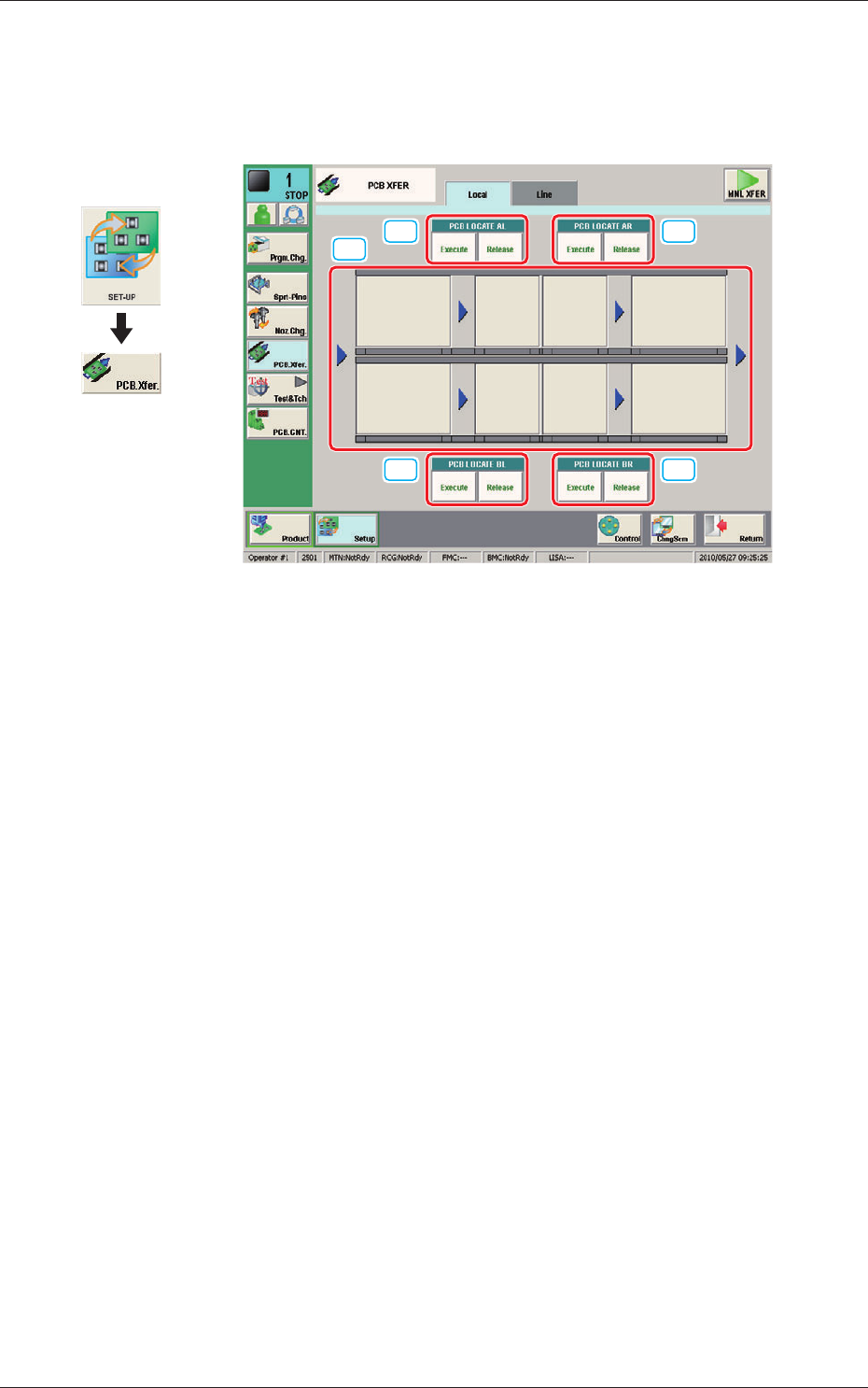
6. "PCB XFER" Window
This window enables the operator to move the PCB on each block on each
lane on the conveyor to the next block.
[1]
[2] [2]
[2] [2]
PCB XFER F9
[1] Conveyor Image Display Pane
Each block in the graphic image of the conveyor is provided with a button
function.
When the [START] button on the operation panel is pressed in 10 seconds
after a conveyor block button, the PCB is transferred to the block position.
[2] PCB LOCATE (PCB LOCATE AL,
AR, BL, BR)
Using these buttons, the PCB positioning is performed for each lane and
each block.
When the [START] button on the operation panel is pressed in 10 seconds
after the [Execute] button, the backup base of the selected stage moves up
and the PCB is positioned.
When the [START] button on the operation panel is pressed in 10 seconds
after the [Release] button, the backup base moves down and the PCB
positioning is released.
Graphic
Development
1005-001
6. "PCB XFER" Window
10
OM-1646
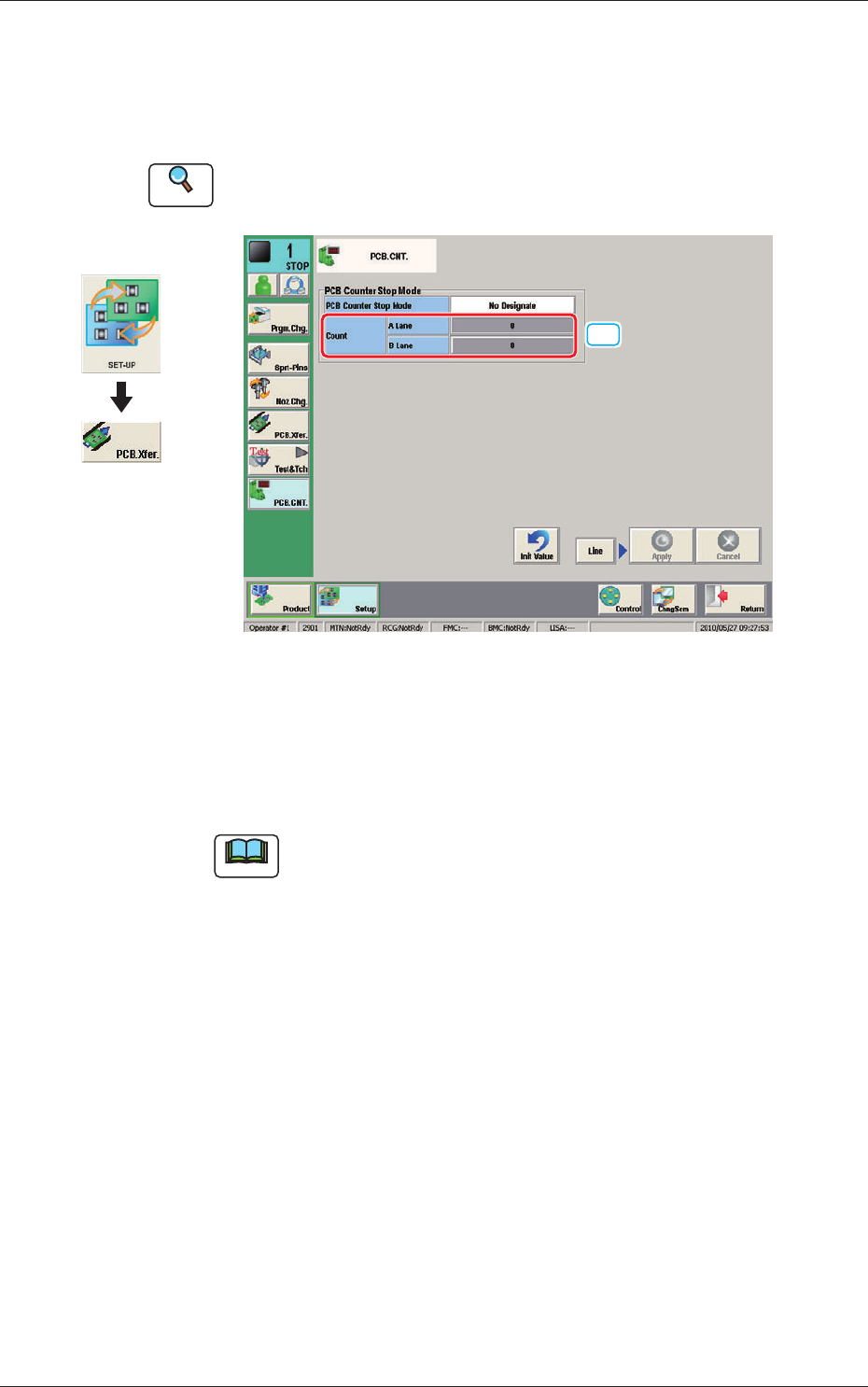
7. "PCB.CNT." Window
This window enables the operator to set the PCB production count for each
lane.
Reference
Refer to the Instruction Manual of the SIGMA-G5 for the information
except for dual transfer.
[1]
PCB. CNT. F10
[1] Count
A Lane, B Lane
The number of produced PCBs for each lane for stopping the machine using
the PCB Counter Stop Mode, is set in this group box.
Note
The set count is displayed in the "Count" data box in the "AUTO. OPN"
window.
Graphic
Development
1005-001
7. "PCB.CNT." Window