OM-1646-001_w.pdf - 第37页
18 OM-1646 1 1.3 Collection of PCB Support Pins and Setup Operation of Conveyor Width (1) Display the "SPR T -PINS CNVR Set-up" wi ndow using the following icon procedure. (2) Select the conveyor in the lane wh…
17
OM-1646
11.2 Selection of Operation Mode
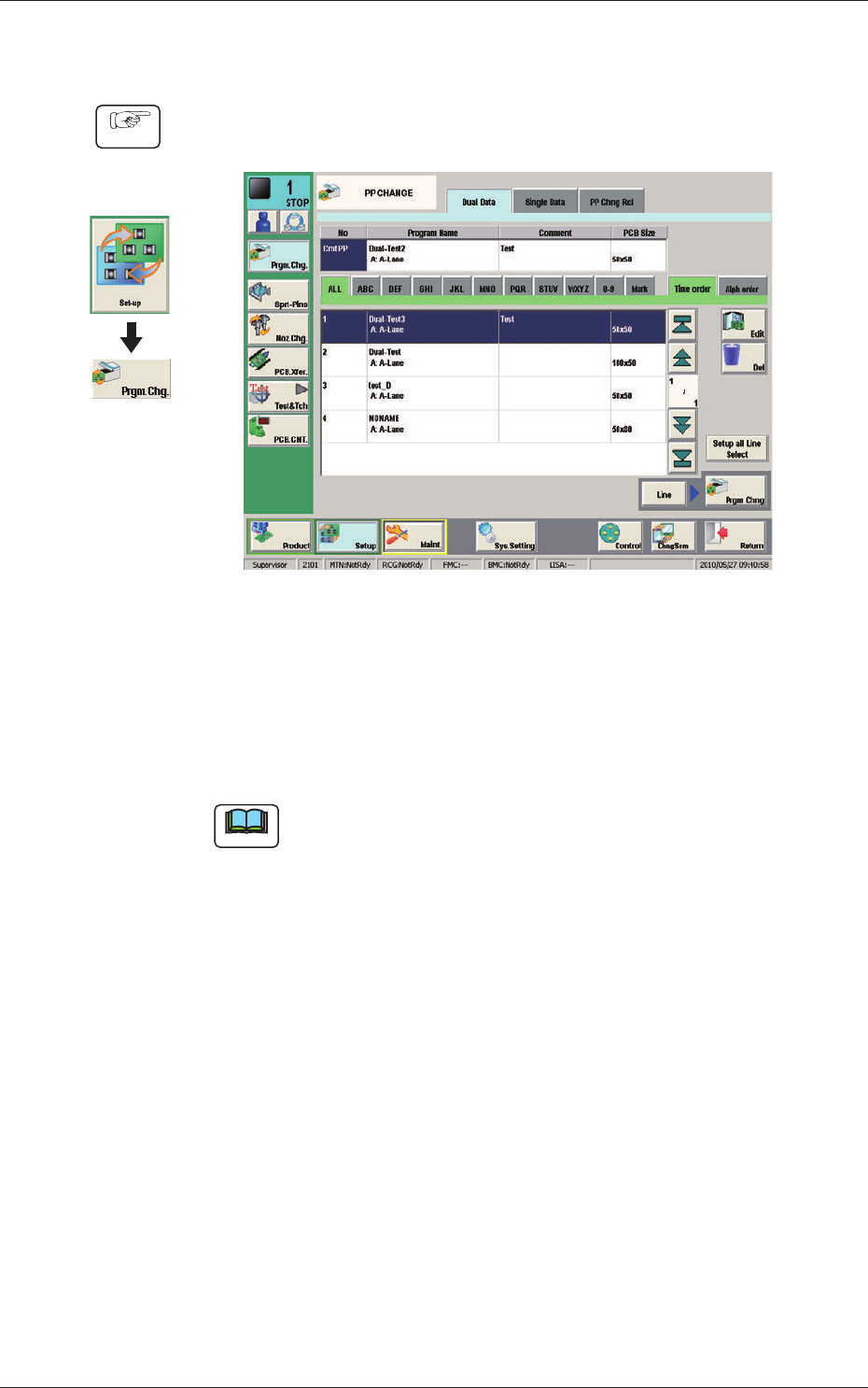
(1) Display the "PP CHANGE" window.
F17
(2) Select the program name to be specied as a current one (production model).
(The corresponding pattern program is selected and the line turns blue.)
(3) Press the [Prgm. Chng] button.
(The current pattern program is changed to the selected one.)
Note
If an error is found in the pattern program, the program change operation
is not executed.
In this case, correct the pattern program and perform the program change
operation again.
Graphic
Development
Procedure
1005-001
11.2 Selection of Operation Mode
18
OM-1646
11.3 Collection of PCB Support Pins and Setup Operation of
Conveyor Width
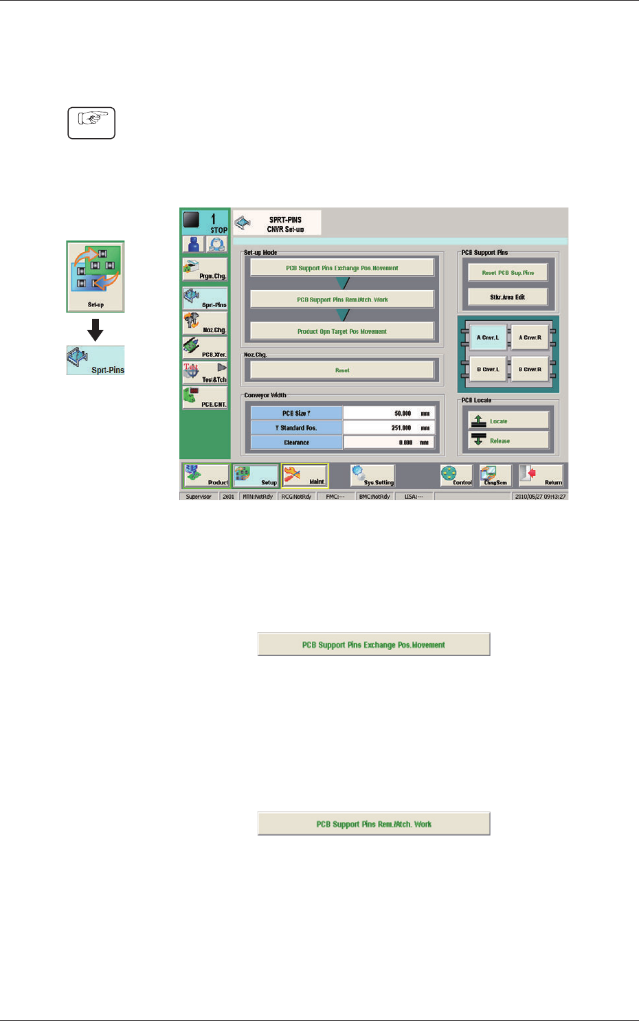
(1) Display the "SPRT-PINS CNVR Set-up" window using the following icon
procedure.
(2) Select the conveyor in the lane where the operation is performed.
F18
(3) Press the [PCB Support Pins Exchange Pos. Movement] button.
After that, press the [START] button on the operation panel in 10 sec.
(The machine retracts the head and maximizes the conveyor width.)
F19
(4) Press the [PCB Support Pins Rem./Atch. Work] button and within 10
seconds, press the [START] button on the operation panel.
(The PCB support pins are arranged onto the positions specied in the
pattern program).
F20
(5) Press the [Product Opn Target Pos.Movement] switch and within 10 seconds,
press the [START] button on the operation panel.
The support pins are moved based on the pattern program where the
conveyor width has been selected.
Graphic
Development
Procedure
1005-001
11.3 Collection of PCB Support Pins and Setup Operation of Conveyor Width
19
OM-1646
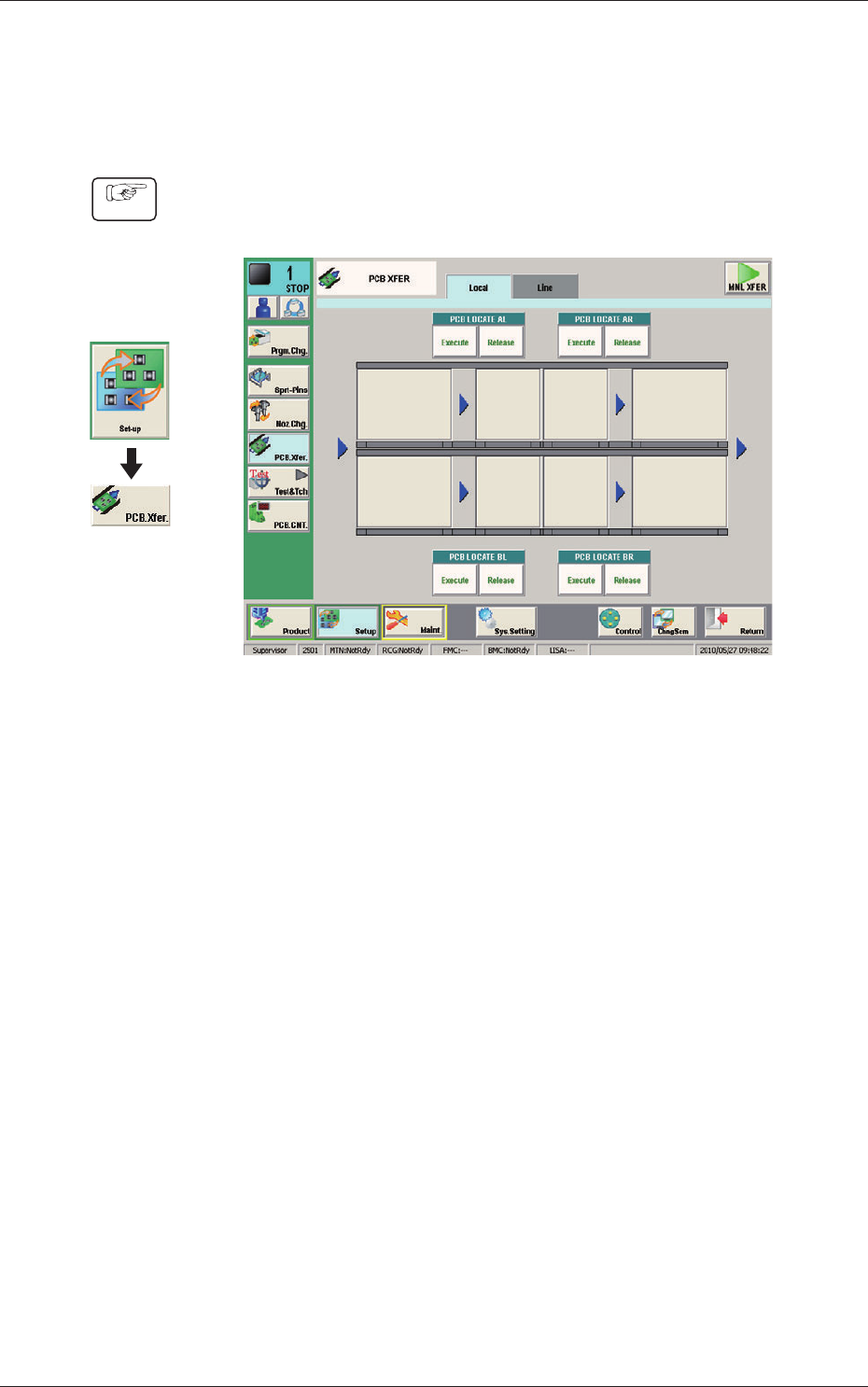
11.4 ConrmationofPCBTransferandPositioning
The following describes how to check the status of the PCB transfer and
positioning in the "PCB XFER" window (a menu of "AUTO OPN").
Procedure
(1) Display the "PCB XFER" window using the following icon procedure.
F21
(2) Send the PCB in the lane where the PCB transfer and positioning status are
conrmed with the input machine.
(3) Select a desired block button (expressed graphically) for "PCB LOCATE 1".
In 10 seconds, press the [START] button on the operation panel to transfer
the PCB.
(4) Conrm that the PCB can be transferred normally and move smoothly
without falling down during the transfer.
(5)
Press the [Execute] button (entitled "PCB LOCATE L").
In 10 seconds, press the [START] button on the operation panel.
(The backup base moves up. )
(6) Press the cover lock switch to turn off the lamp.
(The transparent cover is unlocked. )
Graphic
Development
1005-001
11.4ConrmationofPCBTransferandPositioning