OM-1646-001_w.pdf - 第41页
22 OM-1646 1005-001 12.2 Pattern Program Description 12.2 Pattern Program Description 12.2.1 Common Setting Common Data F23 Graphic Development
21
OM-1646
1005-001
12. Pattern Program
12. Pattern Program
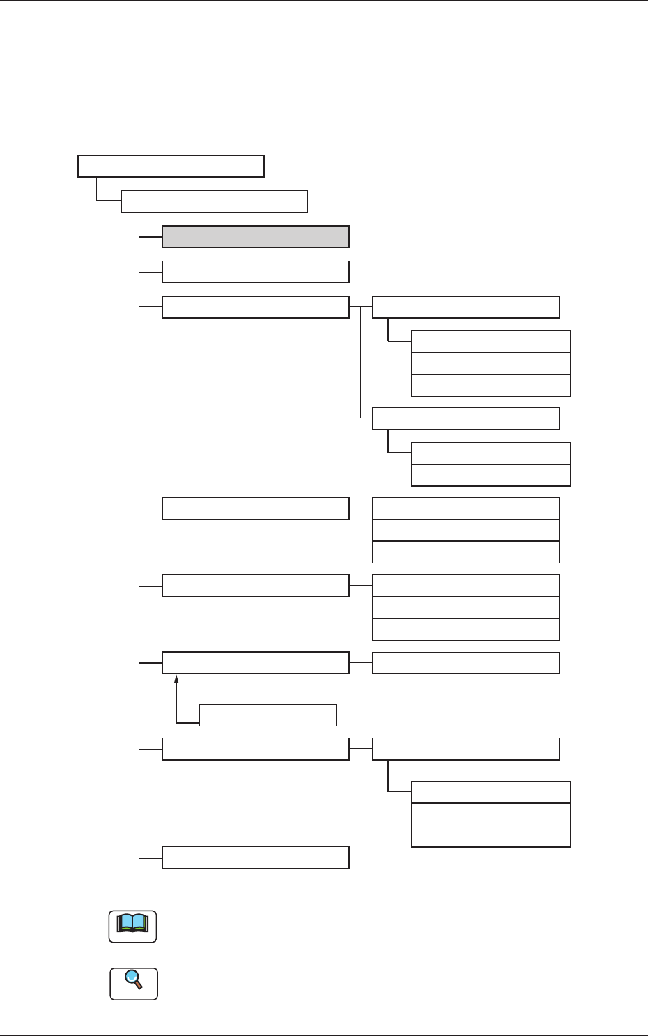
12.1 Composition of Pattern Program
The pattern program for dual transfer consists of the following data items.
Pattern Program
Pattern Program Name
Common SET
PCB
Operation
Control
PL Head/Nozzle
CMPNT PL
Component Library
Component ID
Placement
PCB Recog
Control
PCB locate
Transfer speed
Nozzle Place
Nozzle Stk1
Nozzle Stk2
Function
Mark
Operation
Set-up
Set-up
Support Pin
Block1(2)
Un
Offset
P-data
O-data
HDLG/PL
Composition of Pattern Program F22
Note
The item in gray is to be changed for dual transfer.
Reference
Refer to the Instruction Manual of the SIGMA-G5 for the information
except for dual transfer.
22
OM-1646
1005-001
12.2 Pattern Program Description
12.2 Pattern Program Description
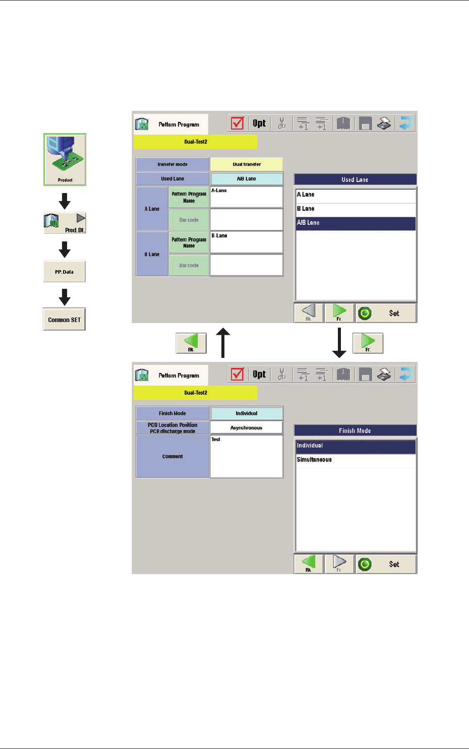
12.2.1 Common Setting
Common Data
F23
Graphic
Development

23
OM-1646
1005-001
12.2 Pattern Program Description
Transfer mode
The transfer mode is set in this selection box.
Dual transfer
When selected, the production is performed using the lanes A and B.
Single transfer
When selected, the production is performed using the lane B.
Note
This function is used when the Y (vertical) in the PCB size is 216 mm or
more.
Used Lane
The lane(s) to be used in the automatic operation is set in this selection box.
A Lane :
When selected, the automatic operation is performed only in
the lane A.
B Lane :
When selected, the automatic operation is performed only in
the lane B.
A/B Lanes :
When selected, the automatic operation is performed both in
the lanes A and B.
Pat
t
ern Program Name for Lane A, Pattern Program Name for Lane B,
Bar code
The pattern program name for each lane is set in this group box.
Max. 32 characters can be used to set.
Available characters are half-width alphabetical / numerical characters and
symbols.