OM-1646-001_w.pdf - 第43页
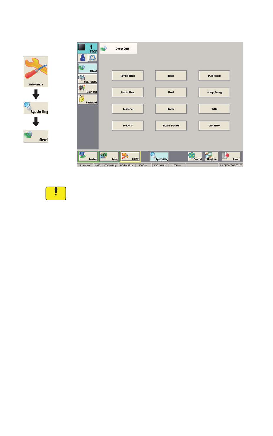
24 OM-1646 1005-001 13. Machine System 13. Machine System Offset Data F24 Notice Do not change the parameters unless nece ssary . These parameters are factory-adjusted upon shipment of the machine. Graphic Development

23
OM-1646
1005-001
12.2 Pattern Program Description
Transfer mode
The transfer mode is set in this selection box.
Dual transfer
When selected, the production is performed using the lanes A and B.
Single transfer
When selected, the production is performed using the lane B.
Note
This function is used when the Y (vertical) in the PCB size is 216 mm or
more.
Used Lane
The lane(s) to be used in the automatic operation is set in this selection box.
A Lane :
When selected, the automatic operation is performed only in
the lane A.
B Lane :
When selected, the automatic operation is performed only in
the lane B.
A/B Lanes :
When selected, the automatic operation is performed both in
the lanes A and B.
Pat
t
ern Program Name for Lane A, Pattern Program Name for Lane B,
Bar code
The pattern program name for each lane is set in this group box.
Max. 32 characters can be used to set.
Available characters are half-width alphabetical / numerical characters and
symbols.
24
OM-1646
1005-001
13. Machine System
13. Machine System
Offset Data F24
Notice
Do not change the parameters unless necessary. These parameters
are factory-adjusted upon shipment of the machine.
Graphic
Development
25
OM-1646
1005-001
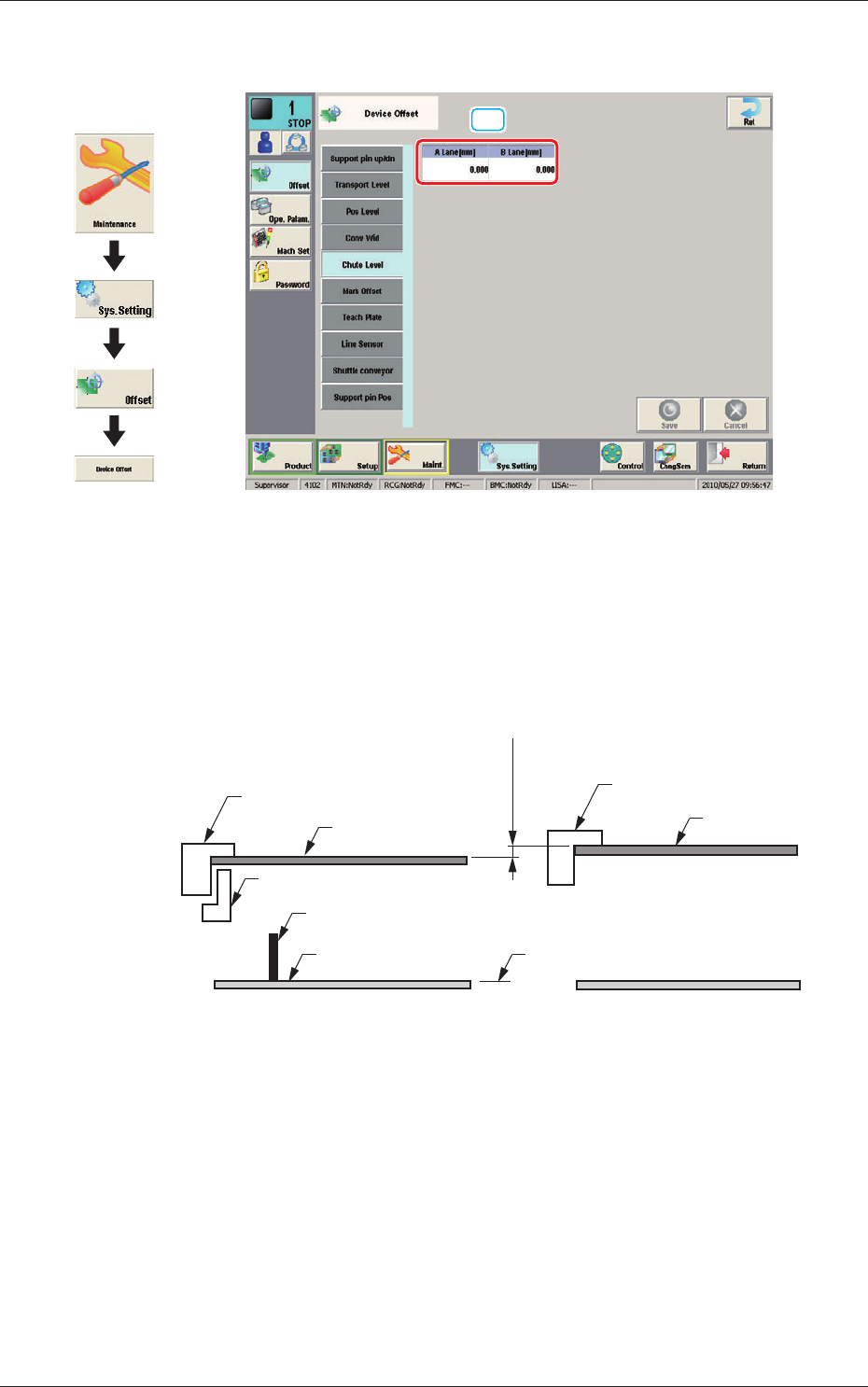
13.1 "Chute Level" Window
13.1 "Chute Level" Window
[1]
Chute Level F25
[1] Chute Level
When the single transfer mode is setup and the PCB size is over 256 mm,
this offset is used to adjust the difference in the positioning height between
the lanes.
Lane A Chute Upper Surface
PCB
(-)
(+)
Support Pin
Backup Base
Difference
A-BL B-BL
Lane B Chute Upper Surface
PCB
2 Clamps
Origin
F25-1
Graphic
Development