OM-1646-001_w.pdf - 第44页
25 OM-1646 1005-001 13.1 "Chute Level" Window 13.1 "Chute Level" Window [1] Chute Level F25 [1] Chute Level When the single transfer mode is setup and the PCB size is over 256 mm, this offset is used …
24
OM-1646
1005-001
13. Machine System
13. Machine System
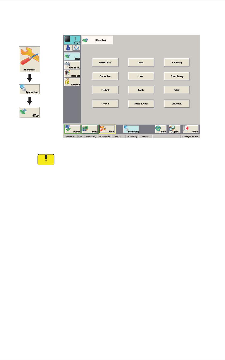
Offset Data F24
Notice
Do not change the parameters unless necessary. These parameters
are factory-adjusted upon shipment of the machine.
Graphic
Development
25
OM-1646
1005-001
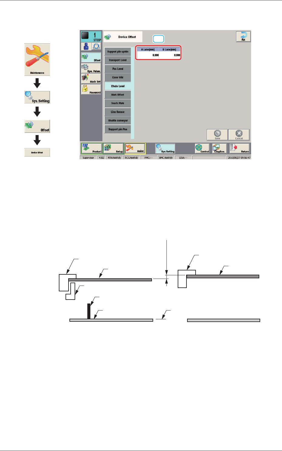
13.1 "Chute Level" Window
13.1 "Chute Level" Window
[1]
Chute Level F25
[1] Chute Level
When the single transfer mode is setup and the PCB size is over 256 mm,
this offset is used to adjust the difference in the positioning height between
the lanes.
Lane A Chute Upper Surface
PCB
(-)
(+)
Support Pin
Backup Base
Difference
A-BL B-BL
Lane B Chute Upper Surface
PCB
2 Clamps
Origin
F25-1
Graphic
Development
26
OM-1646
1005-001
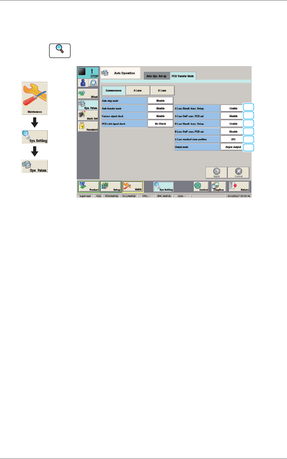
13.2 "PCB Transfer Mode" Tab Sheet
13.2 "PCB Transfer Mode" Tab Sheet
This enables the operator to setup the mode in the input and output machines.
Reference
Refer to the Instruction Manual of the SIGMA-G5 for the information
except for dual transfer.
[1]
[2]
[1]
[2]
[3]
[4]
PCB Transfer Mode F26
•
Commonness
The common setting for the input and output machines to the lanes is
performed.
[1] A Lane Simult. trans. Set-up
B Lane Simult. trans. Set-up
Set "Enable" or "Disable" to determine whether or not the PCB transfer
should be made simultaneously between the input and positioning conveyors
and between the positioning and output conveyors.
Enable
: The simultaneous transfer setup function is
used.
Disable (Independent)
:
The simultaneous transfer setup function is not
used.
Disable (Asynchronous)
:
When the transferred PCB passes the inlet
sensor at the output conveyor, the next PCB
transfer movement is started.
[2] A Lane OutP conv
. PCB out
B Lane OutP conv. PCB out
Set "Disable" or "Enable" to determine whether or not a disengaged PCB
should be detected in the output conveyor section.
Graphic
Development