OM-1646-001_w.pdf - 第46页
27 OM-1646 1005-001 13.2 "PCB T ransfer Mode" T ab Sheet [3] A Lane standard chute position [mm] The standard chute position in the lane A is set in this text box. [4] Output mode The method for the PCB transfe…
26
OM-1646
1005-001
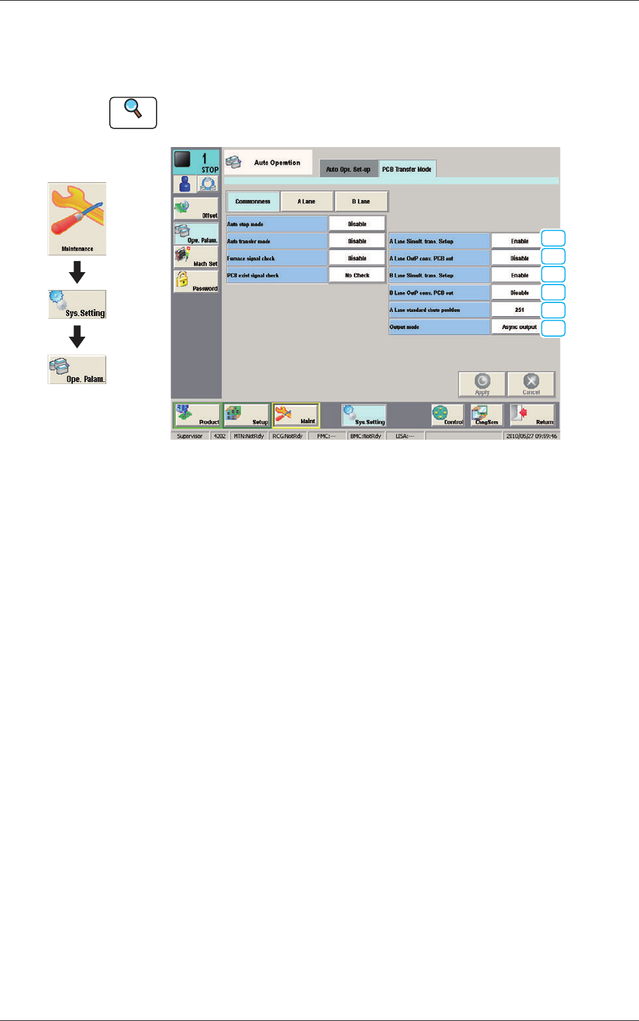
13.2 "PCB Transfer Mode" Tab Sheet
13.2 "PCB Transfer Mode" Tab Sheet
This enables the operator to setup the mode in the input and output machines.
Reference
Refer to the Instruction Manual of the SIGMA-G5 for the information
except for dual transfer.
[1]
[2]
[1]
[2]
[3]
[4]
PCB Transfer Mode F26
•
Commonness
The common setting for the input and output machines to the lanes is
performed.
[1] A Lane Simult. trans. Set-up
B Lane Simult. trans. Set-up
Set "Enable" or "Disable" to determine whether or not the PCB transfer
should be made simultaneously between the input and positioning conveyors
and between the positioning and output conveyors.
Enable
: The simultaneous transfer setup function is
used.
Disable (Independent)
:
The simultaneous transfer setup function is not
used.
Disable (Asynchronous)
:
When the transferred PCB passes the inlet
sensor at the output conveyor, the next PCB
transfer movement is started.
[2] A Lane OutP conv
. PCB out
B Lane OutP conv. PCB out
Set "Disable" or "Enable" to determine whether or not a disengaged PCB
should be detected in the output conveyor section.
Graphic
Development
27
OM-1646
1005-001
13.2 "PCB Transfer Mode" Tab Sheet
[3] A Lane standard chute position [mm]
The standard chute position in the lane A is set in this text box.
[4] Output mode
The method for the PCB transfer to the output machine is setup in this
selection box.
The method for the PCB transfer to the output machine from the two lanes in
the dual transfer mode, is selected from the following items.
Alt output (A lane)
When selected, the PCBs on which the component placement has been
completed, are discharged alternatively from the Lane A.
Alt output (B lane)
When selected, the PCBs on which the component placement has been
completed, are discharged alternatively from the Lane B.
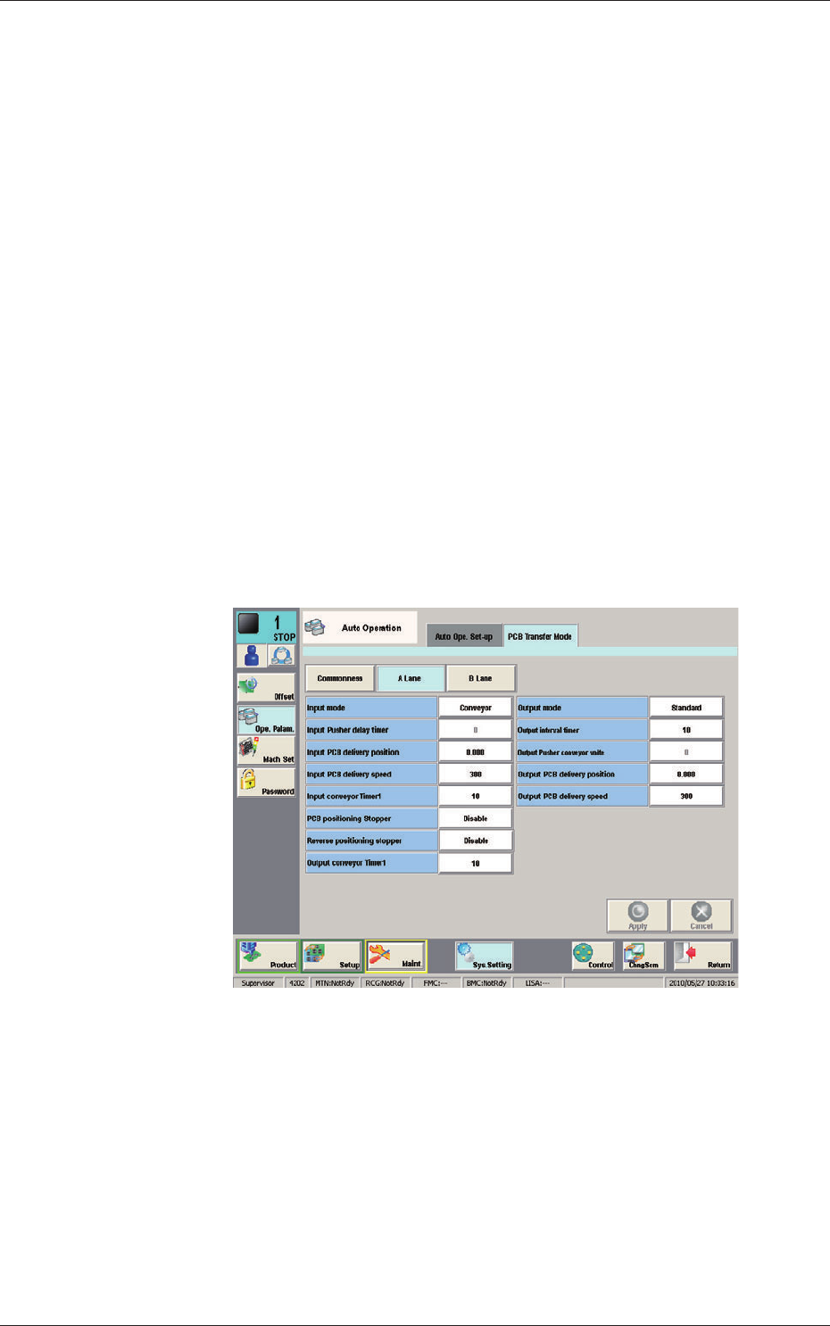
•
A Lane, B Lane
The setting for the input and output machines for each lane is performed.
F27
28
OM-1646
1005-001
14. Maintenance
14. Maintenance
This session describes how to perform inspections, cleaning, lubrication, and
adjustment to keep the machine in good shape.
Be sure to periodically perform the maintenance tasks.
14.1 Outline of Maintenance
14.1.1 Notes on Maintenance
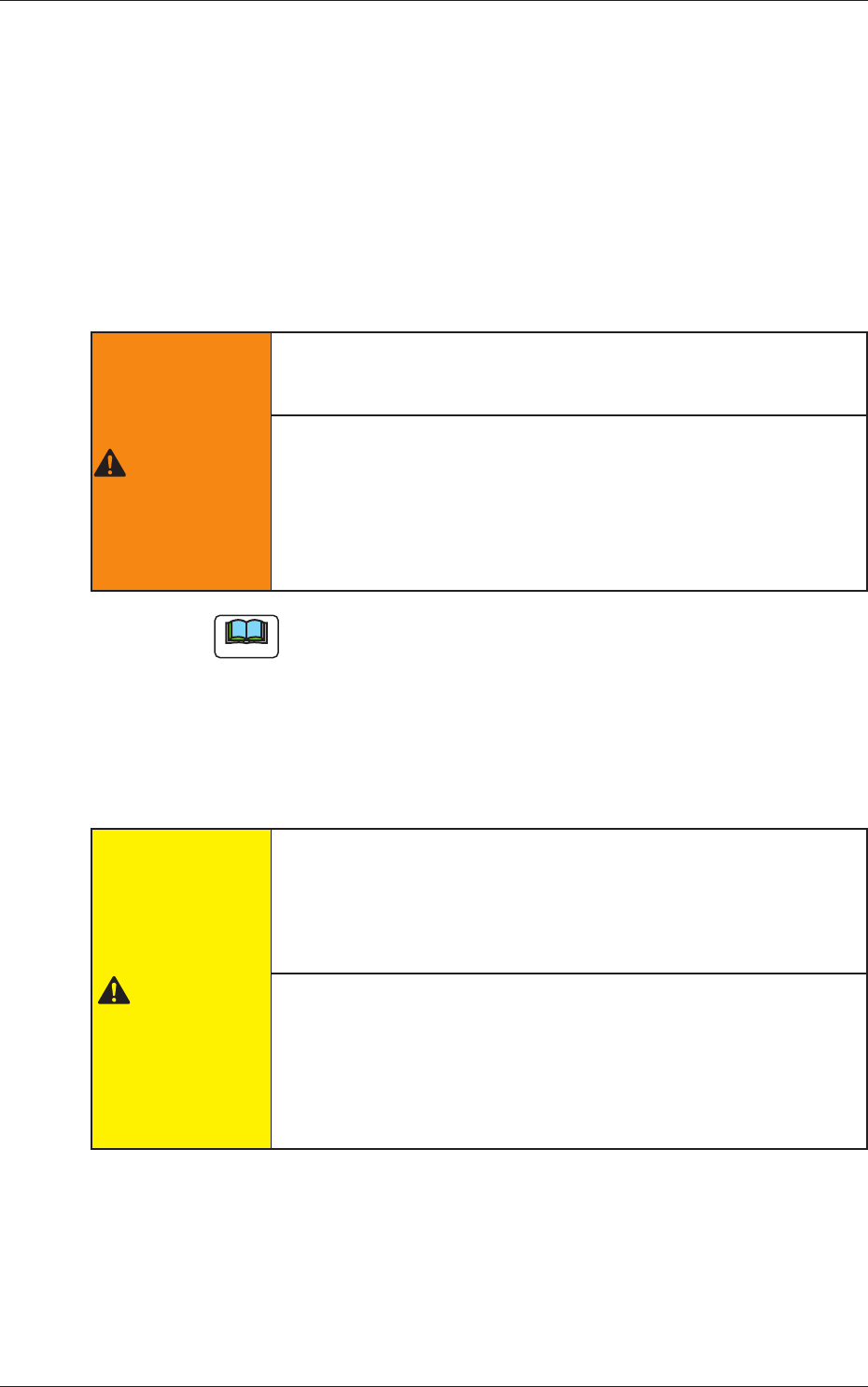
WARNING
Only a well-trained service person should perform maintenance
taskscarefullythroughthespeciedprocedures.
Before maintenance work, shut off the power breaker and lock
the power breaker with the padlock.
Designate a person who can have charge of the padlock key.
If the provided padlock is lost or damaged, purchase its
substitute.
Note
(a) Preliminary preparation is required for some maintenance tasks with
the power being supplied.
(b) Note that the linear measure sensors must be cleaned with the power
being supplied.
Although the load power to the motors, etc., is turned OFF when
the transparent cover is opened, the maintenance must be performed
carefully because you have to put your hand(s) inside the machine.
CAUTION
Even when the power breaker is set to "OFF", the primary line
is powered, making it possible to cause an electric shock.
Be sure to completely stop the power supply to the machine before
maintenance work.
Residual voltages may remain behind for a few minutes in the
internal devices of the machine after power interception.
Before performing maintenance work, wait until the charge lamps of
the dc power supply and the servoamplier go "OFF" in 10 minutes
or more after the power breaker is set to "OFF".