OM-1646-001_w.pdf - 第85页
66 OM-1646 Item Description 13. Input and Output Interfaces Conforming to the specications of the SMEMA communications. 17. Specications 1005-001
65
OM-1646
1005-001
17. Specications
Item Description
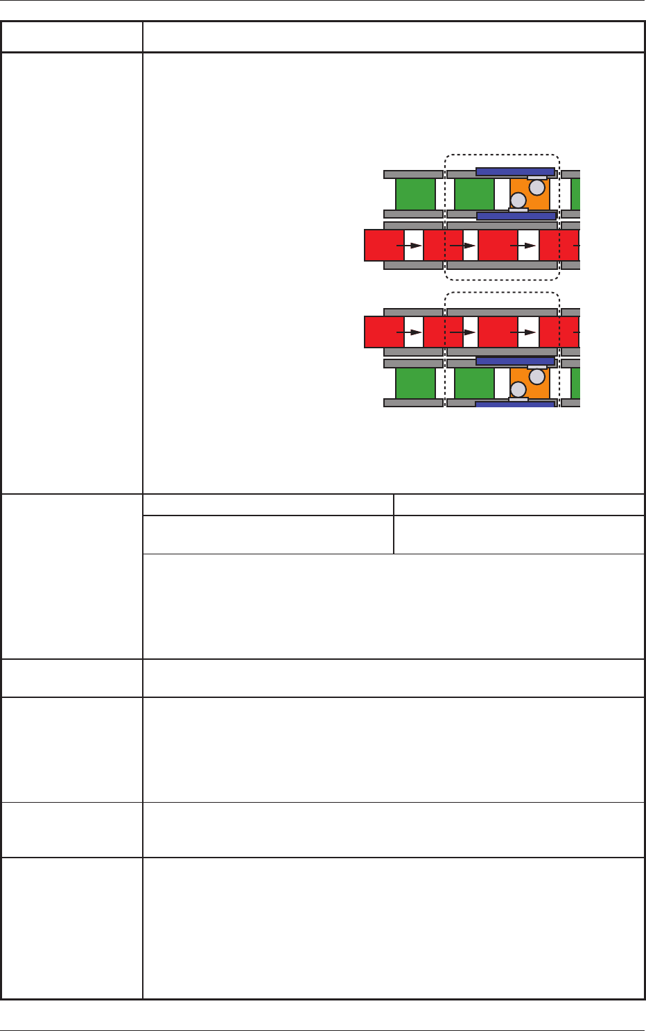
7. Outline of Actions The machine starts component placement on either one (positioned one) of the PCBs
on the
two transfer lanes.
After the machine has completed component placement on the PCB on one lane, it
starts placement on the PCB on the other lane.
Lane A : Placement
Lane B : Transfer
Lane A : Transfer
Lane B : Placement
Process
Position
Process
Position
Since the PCBs are transferred alternately, components are placed on the PCB on either
one of the lanes, making it possible for the machine to continuously place components
regardless of which PCB transfer should take place rst.
Ref.: The PCB transfer time becomes as if it were "0" (zero).
8. PCB Replacement
Time
Dual Transfer Mode Single Transfer Mode
0 second Note W
ithin
2 seconds
(260 mm or less in PCB length)
Notes : (a) When "Operation Mode 1" is selected, the transfer time becomes as if it
were "0"
(zero) because PCBs are transferred alternately on both lanes.
However,
"the previously placed component thickness or currently placed
component thickness should be 12.7 mm or less" as the condition.
(b) In the case that the production
is continued only in one side, the time is the
same as in the single transfer mode.
9. Transfer Height 905 mm (Transfer Reference Height)
Note
: As
for SMEMA height, another option is required.
10. Automatic Setup
function
•Automatic Width
Setup Function
Standard Design with Two Modes; Dual Transfer Mode and Single Transfer Mode
•Backup Up/Down Function
Standard Design with Divided Type for Dual Transfer
• Support Pin Change
Standard Design with the Support Pin Automatic Setup Function
11. Pattern Program In Operation Mode 1, PCBs are transferred alternately through asynchronous actions.
Therefore, the
pattern programs shall be prepared individually for each PCB transfer
lane.
12. Hardware
Signal Connection for Input and Output Machines
Two types of I/F systems are provided independently
for both input and output
machines.
Signal paths
(paths for signals from/to the input & output machines and the furnace)
can be connected to the I/F board of the input and output machines.
Signal Connections in Dual and Single Transfer Modes
Dual Transfer Mode : 2 Systems
Single T
ransfer Mode : 1 System

66
OM-1646
Item Description
13. Input and Output
Interfaces
Conforming to the specications of the SMEMA communications.
17. Specications
1005-001

67
OM-1646
1005-001
17. Specications