MEC-CP842-1.0E.pdf - 第119页
Replacing Consumable Parts >> Vacuum Pump Internal Vanes and Bearings MEC-CP842-1.0E 6-11 3 Open the belt cover . 4 Remove the pulley and the pulley fan, then remove the vacuum pump from the table. Caution:The air …
Replacing Consumable Parts >> Vacuum Pump Internal Vanes and Bearings
6-10 MEC-CP842-1.0E
6.7 Vacuum Pump Internal Vanes and Bearings
Point
The vacuum pump blade consists of 6 vanes. Broken vanes can cause abnormal vac-
uum pump noise, and may reduce the vacuum force. When replacing the vanes, the
bearings must also be replaced.
Procedure
Disassembly
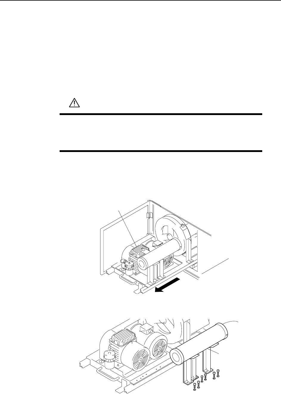
1 Pull out the vacuum pump. (For this procedure, refer to section 6.6 "Vacuum
Pump Belt").
2 Remove the duct together with the bracket.
WARNING
• Turn the main power off before performing this procedure.
• Do not touch the vacuum pump immediately after operation
because it may be extremely hot. Allow the pump to cool before
beginning this procedure.
C746M4013
Vacuum pump
C746M401
4
Duct
Replacing Consumable Parts >> Vacuum Pump Internal Vanes and Bearings
MEC-CP842-1.0E 6-11
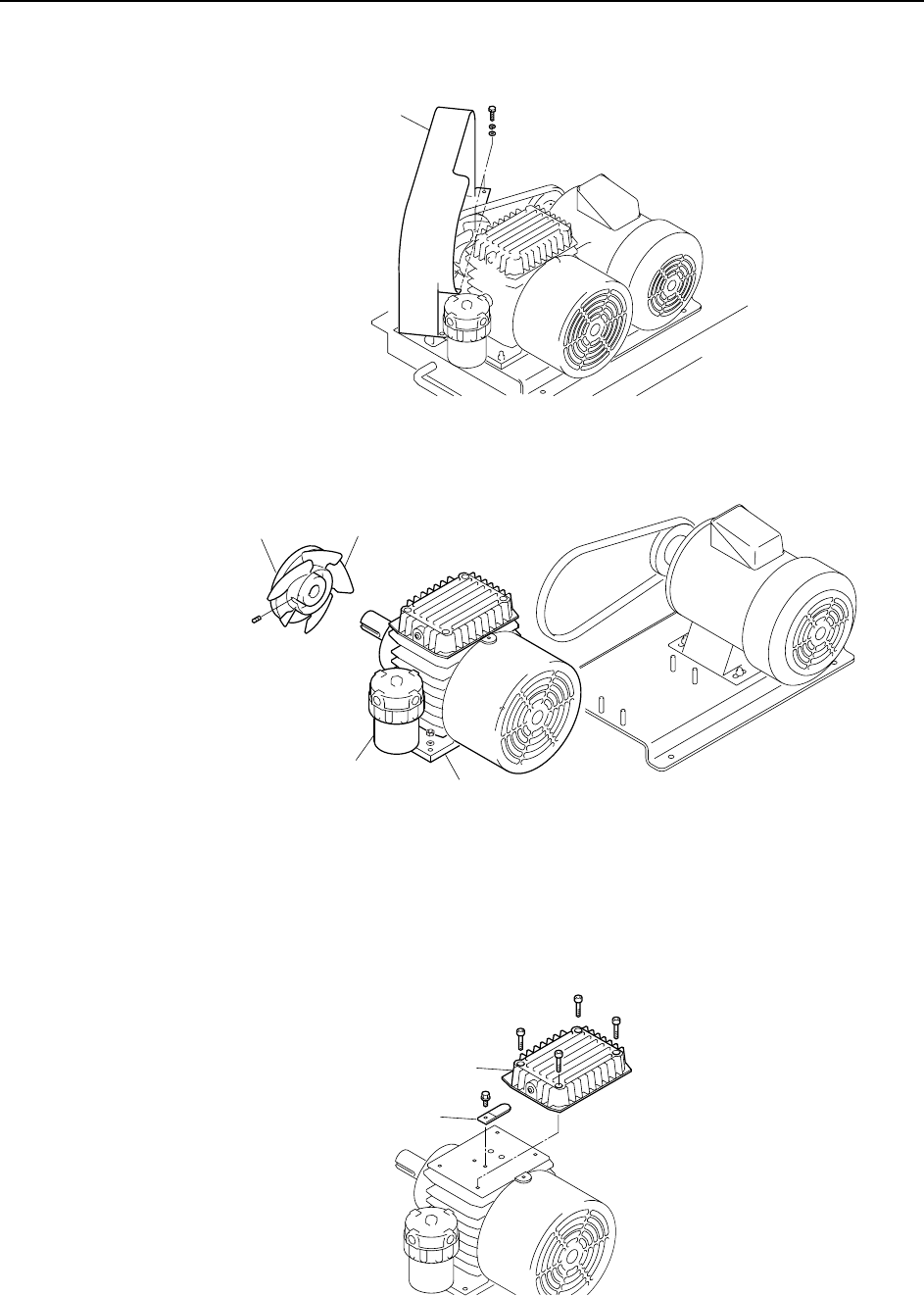
3 Open the belt cover.
4 Remove the pulley and the pulley fan, then remove the vacuum pump from the
table.
Caution:The air filter should not be removed from the vacuum pump for the following reasons.
1. There is a possibility of damage to the pump plumbing or air filter housing.
2. Metal fragments or other dust from the plumbing may get into the pump.
5 Remove the silencer case and the check valve.
C746M4015
Belt cover
C746M4016
Pulley
Pulley fan
Vacuum pump
Air filter
C746M4017
Silencer case
Check valve
Replacing Consumable Parts >> Vacuum Pump Internal Vanes and Bearings
6-12 MEC-CP842-1.0E
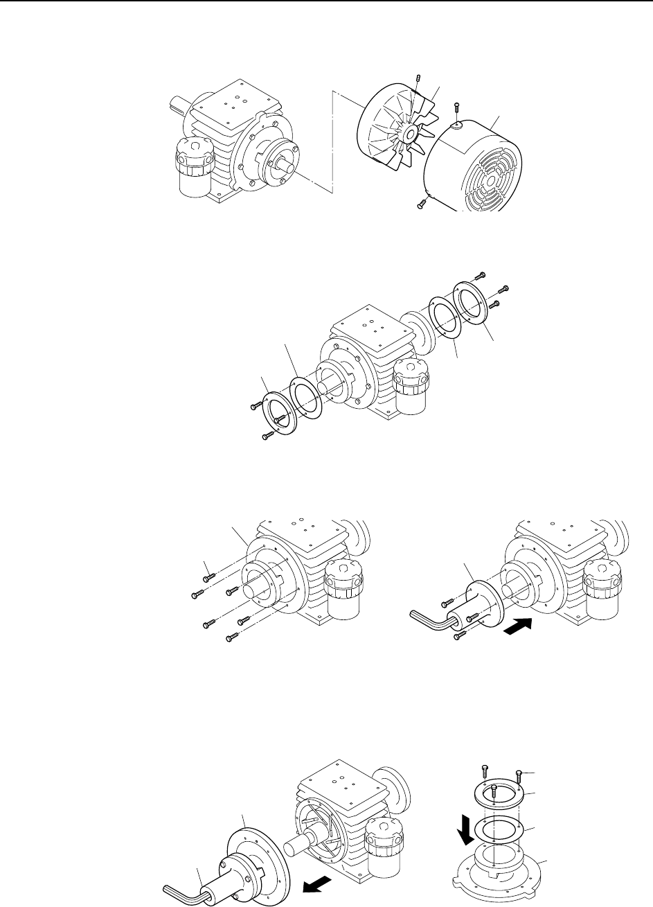
6 Remove the cooling fan cover and the cooling fan.
7 Remove the bearing retainers and liners.
8 Remove the side plate "B" mounting bolts, then use these bolts to secure the
special tool (Jig No. Z9913AWPJ9470) to side plate "B".
9 Pull on the special tool to remove side plate "B".
Remove the special tool from side plate "B", then install the bearing retainer
and liner (removed at step 7 above) on side plate "B". Do not tighten the bolts
fully at this time (back off 1 mm from fully tightened condition).
Note: Use care to avoid scratching side plate "B" and the inner surface of the cylinder.
C746M4018
Fan cover
Cooling fan
C746M4019
Bearing retainer
Bearing retaine
r
Liner
Liner
C746M4020
Mounting bolts
Side plate B
Special tool
C746M4021
Side plate B
Special tool
Bearing retainer
Bolt
Liner
Side plate