MEC-CP842-1.0E.pdf - 第141页
Adjustments >> Station Adjustments MEC-CP842-1.0E 7-5 3 Ensure that there is a gap of 0 ~ 0. 5 mm between the movable cutter lower sur- face and the cutter unit base. 4 Use the cam handle to rotate the cam to 194°.…
Adjustments >> Station Adjustments
7-4 MEC-CP842-1.0E
7.1.2 Waste Tape Cutter (ST1)
Point
The waste tape cutter cuts waste tape that is advanced beyond the end of the feeder.
Vacuum takes the cut tape into the waste tape box at the front side of the machine.
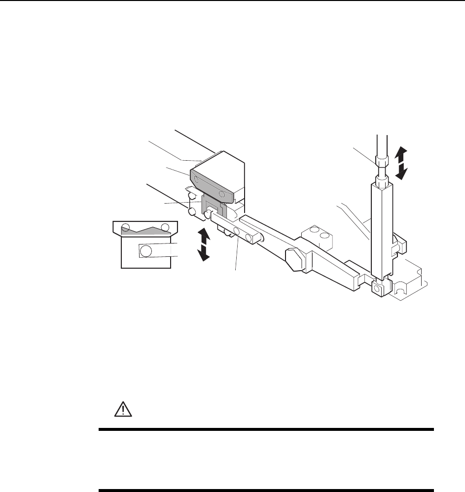
Rotate the rod to adjust the extension of the movable cutter behind the fixed cutter.
Adjustment Procedure
1 Press the EMERGENCY STOP button. This turns off the 200V power.
2 Use the cam handle to rotate the cam to 0°.
WARNING
• Press EMERGENCY STOP before performing this procedure.
• Exercise extreme caution when working on the machine if the cam
is not at its origin (0 deg.) Spring recoil can rotate the cam inde-
pendently.
Adjustment rod
Fixed cutter
Movable cutter
Cutter lever
C7SM4007a
Adjustments >> Station Adjustments
MEC-CP842-1.0E 7-5
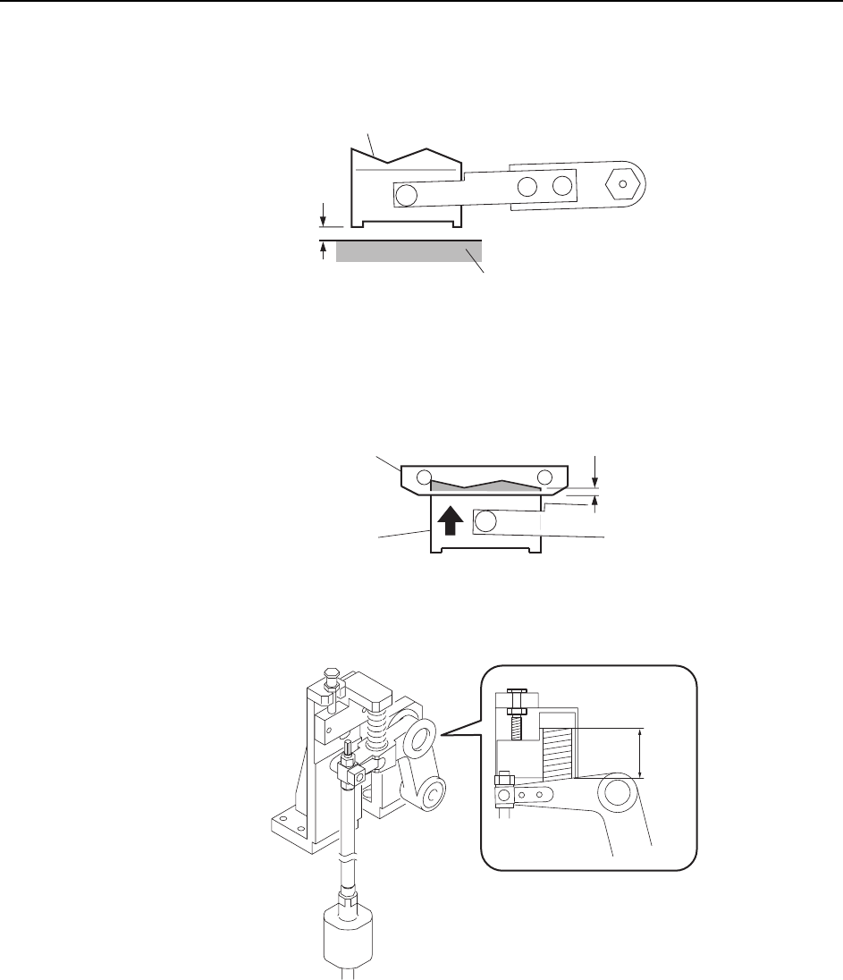
3 Ensure that there is a gap of 0 ~ 0.5 mm between the movable cutter lower sur-
face and the cutter unit base.
4 Use the cam handle to rotate the cam to 194°.
5 Adjust the rod so that the movable blade and fixed blade engages by 0.5 to 1.0
mm.
6 Ensure that the spring length is 38 mm.
0~0.5 mm
C7SM4009b
Movable cutter
Cutter plate
Fixed cutter
Movable cutter
0.5~1.0 mm
C7SM4008a
C7SM4010b
38 mm
Adjustments >> Station Adjustments
7-6 MEC-CP842-1.0E
7.1.3 Nozzle Vertical Movement During Pickup
(ST1)
Slider Adjustment
Adjust the height of the slider to ensure that the cam follower can travel smoothly
through the slider and along the cam groove.
1 Press the EMERGENCY STOP button. This turns off the 200V power.
2 In order to remove the nozzle shaft assembly, it is first necessary to remove the
upper clutch. Set the cam angle to 0° (nozzle shaft between ST9 and ST10) and
hold the shaft with a wrench (DCPJ0450) while loosening the Allen bolt. Turn
the loosened bolt by hand and then remove the clutch. (See illustration on the
next page.)
Caution:Remove the G or O nozzle shaft assemblies, because the turret slots are wider for these 2
shafts. Some maintenance is much more difficult with other turret slots.
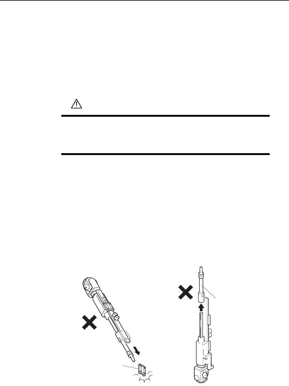
3 Remove the linear guide clampers and vacuum hose, then remove the nozzle
shaft assembly.
Caution:When handling the nozzle shaft assembly exercise caution to ensure that the linear guide
and outer shaft do not slide off the end of the shaft.
WARNING
• Press EMERGENCY STOP before performing this procedure.
• Exercise extreme caution when working on the machine if the cam
is not at its origin (0 deg.). Spring recoil can rotate the cam inde-
pendently.
Outer shaft
C7SM4011a
Linear guide