MEC-CP842-1.0E.pdf - 第144页
Adjustments >> Station Adjustme nts 7-8 MEC-CP842-1.0E 4 Move the turret slot for the removed nozzle sha ft to ST1, then turn on the so le- noid Y031 ST1 PICKUP SOL ENGAGED. 5 Set the cam a ngle to 0°, and position…
Adjustments >> Station Adjustments
MEC-CP842-1.0E 7-7
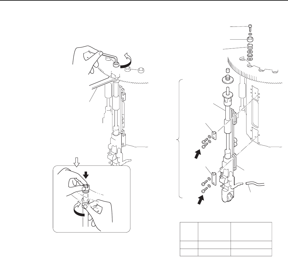
Caution:Do not disassemble nozzle shaft assemblies carelessly. Special equipment and skills are
required to remove and reassemble a nozzle shaft. Such procedures should be attempted
only by maintenance staff who have attended training at Fuji and are equipped with the nec-
essary tools.
Outer
shaft
Clamper
Wrench
( DCPJ0450 )
Clutch
Bolt
Spring
Linear guide
Vacuum hose
A
B
Part
Bolt
size
Torque
Nm ( Kgf/cm )
A
B
M4
M4
2 ( 20 )
2 ( 20 )
Clamper
C7SM4012a
Nozzle
shaft
assembly
Caution : Washers may move when the
bolt is loosened because of the
spring under the clutch.
Rotate the placing
head while holding
the bolt with finger.
Adjustments >> Station Adjustments
7-8 MEC-CP842-1.0E
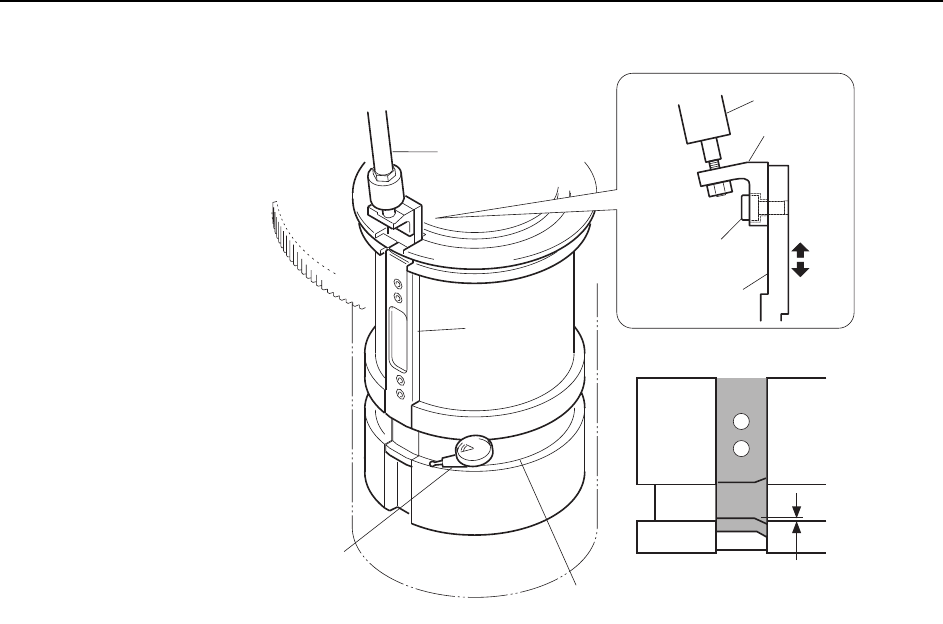
4 Move the turret slot for the removed nozzle shaft to ST1, then turn on the sole-
noid Y031 ST1 PICKUP SOL ENGAGED.
5 Set the cam angle to 0°, and position the dial gauge as shown in the figure
above.
6 Check that the vertical difference between the groove on the slider and the tur-
ret groove is 0 to 0.02 mm. If this range is exceeded, loosen the bolt on the rod
bracket and make the required adjustments to the height of the slider.
7 Tighten the bolt while maintaining the height of the slider.
8 Check the distance between the cam grooves again.
Note: If the alignment of the grooves cannot be adjusted to the correct range, then adjust the height
of the rod that controls the vertical movement of the bracket.
9 Reattach the nozzle shaft assembly in the original location. Reverse the
removal procedures and use the clutch alignment jig to reattach the shaft.
Caution:The nozzle shaft assembly is exclusive to the CP-842E/842ME and cannot be used on other
machine types, such as CP-733E, CP-743ME, or CP-743E.
Slider
Rod
0~0.02 mm
C7SM4013b
Dial gauge
Rod
Bracket
Bolt
Slider
Cam groove
Adjustments >> Station Adjustments
MEC-CP842-1.0E 7-9
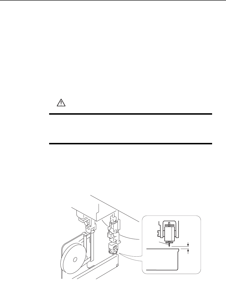
Confirming the Pick-up Height
Ensure that the nozzle descends low enough to pick up a part set in the feeder. Con-
firm that the mechanical valve movement switches on the vacuum for part pick-up.
1 Set a W8 x P4 mm feeder (with tape leaf removed) at the D1 position.
2 Move the feeder to ST1 by pressing [Position] - (Position) [D1-axis] - enter [1] -
[OK] - START.
3 Check that the NZ-axis is stopping at the position specified at the "PICK UP
POS. NZ" item in Proper data.
4 Push the EMERGENCY STOP button, which disables the 200V power but
leaves the 100V power on.
5 Set the cam angle to 0°, then turn the first nozzle solenoid valve on to activate
the cam lever.
6 Use the cam handle to rotate the cam to 170°.
7 Ensure a space of 0.65 mm between the tip of the nozzle and the feeder (pick-up
height).
WARNING
• Press EMERGENCY STOP before performing this procedure.
• Exercise extreme caution when working on the machine if the cam
is not at its origin (0 deg.). Spring recoil can rotate the cam inde-
pendently.
0.65 mm
Feeder
Nozzle
C7SM4014