MEC-CP842-1.0E.pdf - 第153页
Adjustments >> Station Adjustments MEC-CP842-1.0E 7-17 Feeder Check Sensor Position Adjustment 1 Press the EMERGENCY STOP button to tu rn off the 200V power , leaving only the 100V power on. 2 Set the positioning j…
Adjustments >> Station Adjustments
7-16 MEC-CP842-1.0E
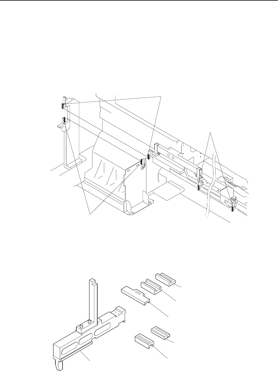
7.1.5 Feeder Height Error Detection (ST1)
Point
To detect the positions of the feeders, two sets of sensors are used at each of the retract
areas (D1, D2). Another pair of sensors is located at the pickup position, so there are
five sets in total.
A dedicated jig is used to position these sensors. The sensitivity of the sensors must
also be adjusted.
Note: This diagram shows the CP-842ME D1 arrangement, but the D2 arrangement is the same.
The jig used to adjust the sensor positions is shown below.
Feeder check sensor
(D1 retract area upper direction check)
Feeder check sensor
(D1 retract area lower direction check)
Feeder check sensor
(Pickup area upper direction check)
C7SM4022a
Positioning jig body
(ADCPJ8020)
Block
(DCPJ0040)
Block
(DCPJ0050) < For CP-842ME >
Block
(DCPJ0060)
Block
(DCPJ0070)
Block
(DGPJ5070) < For CP-842E >
C7SM4049b
Adjustments >> Station Adjustments
MEC-CP842-1.0E 7-17
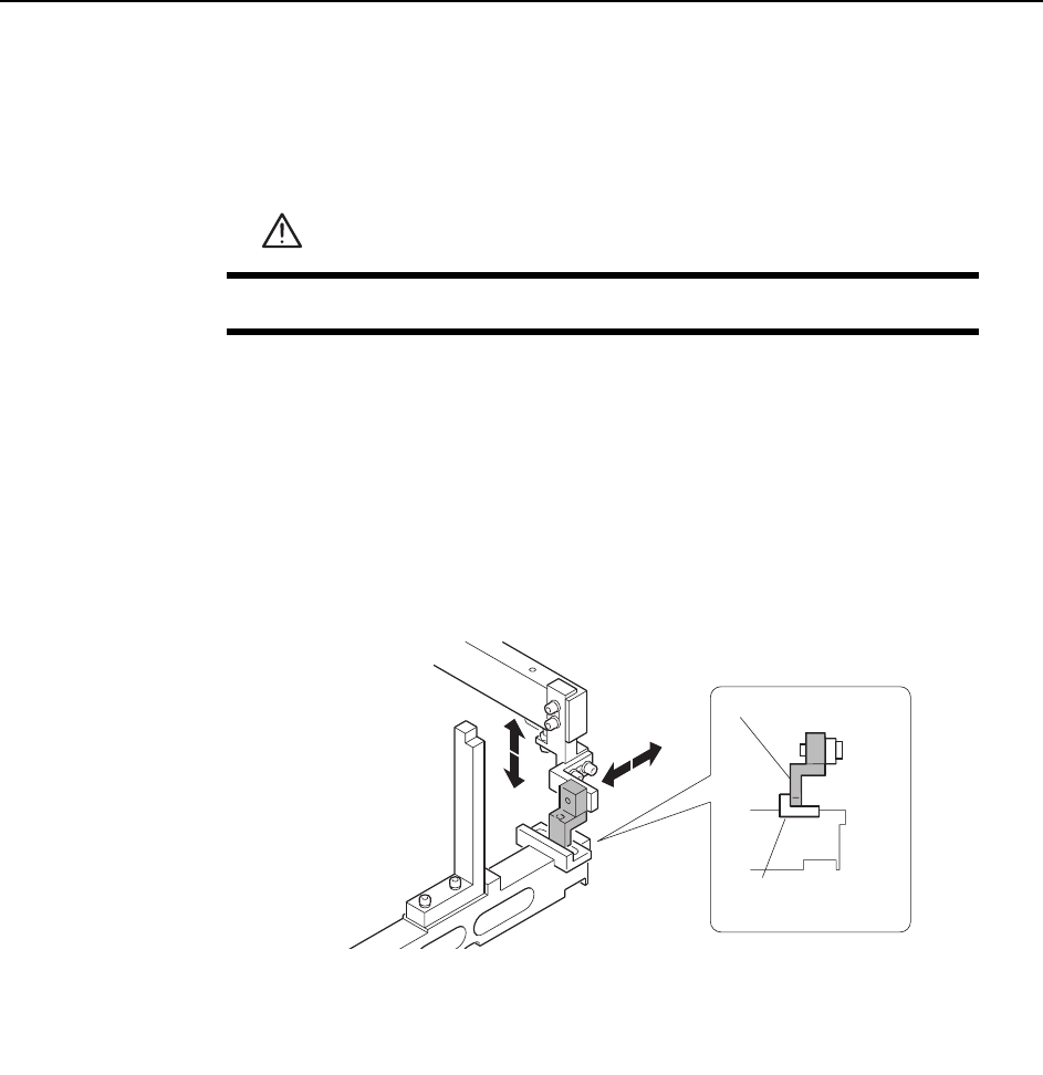
Feeder Check Sensor Position Adjustment
1 Press the EMERGENCY STOP button to turn off the 200V power, leaving only
the 100V power on.
2 Set the positioning jig body on a feeder pallet.
3 Use the inching keys to position the feeder pallet and bring the positioning jig
body within the vicinity of the sensor in question.
4 Attach a block appropriate for each sensor within the jig and then adjust the
sensor position.
Pick-up Area
WARNING
Press EMERGENCY STOP before performing this procedure.
Block
(DCPJ0040)
Sensor bracket
C7SM4050a
Adjustments >> Station Adjustments
7-18 MEC-CP842-1.0E
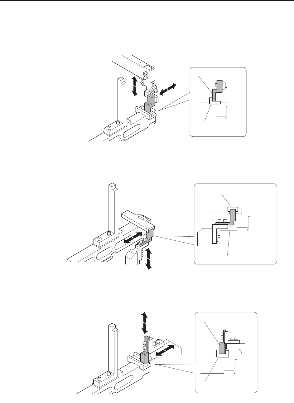
D1, D2 Retract Area (Upper direction check)
Inner sensor
Outer sensor
<CP-842E>
<CP-842ME>
Block
(DCPJ0040)
Sensor bracket
C7SM4050a
C7SM4057a
Sensor bracket
Block (DGPJ5070)
Block (DCPJ0050)
C7SM4051a
Sensor bracket