MEC-CP842-1.0E.pdf - 第159页
Adjustments >> Station Adjustments MEC-CP842-1.0E 7-23 Sensor Amplifier Adjustment Open the front cover and follow the procedures below . 1 Check that the output DIP switch is set to "L ON". 2 Set the pow…
Adjustments >> Station Adjustments
7-22 MEC-CP842-1.0E
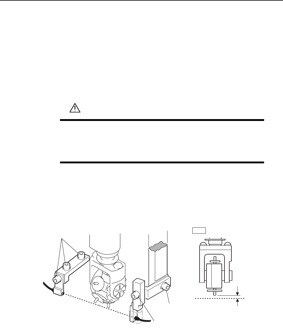
7.1.6 Large Parts Check Sensor (ST2)
Point
The machine has a sensor at station 2 that checks for large parts (height of 1 mm or
greater). The machine stops immediately if a part is not detected.
Sensor Position Adjustment
1 Press the EMERGENCY STOP button. This turns off the 200V servo power.
2 Use the cam handle to rotate the cam to 200°.
3 Adjust the sensor bracket positions so that the sensor beam passes 0.7 ~ 0.8 mm
below the nozzle tip. Use a feeler gauge etc. to check the sensor reaction while
adjusting the vertical position.
4 When complete, pick up a large part to check the sensor reaction.
WARNING
• Press EMERGENCY STOP before performing this procedure.
• Exercise extreme caution when working on the machine if the cam
is not at its origin (0 deg.). Spring recoil can rotate the cam inde-
pendently.
0.7~0.8 mm
Horizontal adj. bolt
Adjustment bolts
ST2
Light beam
Light beam
C7SM4024a
Vertical adj. bolt
Adjustments >> Station Adjustments
MEC-CP842-1.0E 7-23
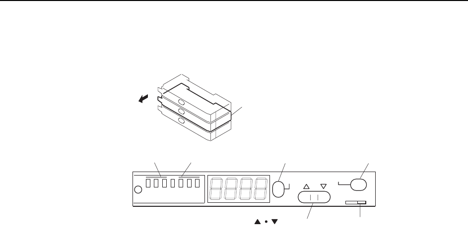
Sensor Amplifier Adjustment
Open the front cover and follow the procedures below.
1 Check that the output DIP switch is set to "L ON".
2 Set the power modes and timer modes as explained below.
2-1. Press and hold down the MODE button for three seconds or more to
change the display to "turb".
Use the up and down arrow buttons to set the power mode to "SUPER".
2-2. Press the MODE button to change the display to "dLy".
Use the up and down arrow buttons to set the timer mode to OFF.
2-3. Press the MODE button again to return the display to the original state.
3 Press the MODE button to toggle the display from the light value, to the per-
centage value (value + "P"), and then back to the light value.
Ensure that the figures for all the sensors are above the minimum values shown
below.
200 digit (target: 500 digit)
Note: The sensor should be replaced when the light reading is at approximately 4095.
Check the following items if the light reading does not reach the minimum
value.
a Check the position of the sensor bracket.
b Check that the sensor is correctly attached to the sensor bracket.
c Check the positioning of the fiber and attachment tips.
d Check whether the fiber and amp connections are correctly inserted.
e Check the condition of the fiber wiring.
4 Change the display to show the percentage value by pressing the mode button to
toggle the display as required.
5 Use the up and down arrow buttons to set the value to 200.
Note: The arrow buttons cannot be used if the display reads 999P. In this situation, press the SET
button twice to revert the display to 100P.
Large parts check sensor amplifier
Open the cover
SET
SUPER
TURBO
FINE
SET
40ms
10ms
OFF
MODE
D ON L ON
C7SM4025a
Output dip switch
[MODE] button[SET] buttonPower mode Timer mode
[ ] button
Adjustments >> Station Adjustments
7-24 MEC-CP842-1.0E
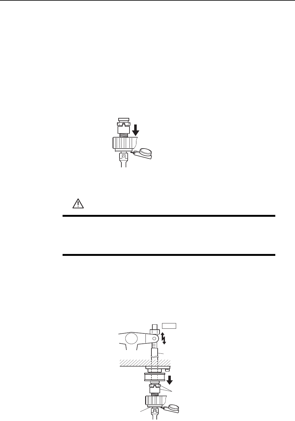
7.1.7 Pre-theta Movement (ST2)
Point
After the nozzle picks up the part at station 1, pre-theta at station 2 rotates the nozzle
by 90°, 180° or -90° depending on the settings in the production program.
Clutch Meshing Check
Perform this check on the LOW nozzle.
Note: The LOW nozzle refers to the nozzle shaft with the shortest vertical stroke when pushed
down by the clutch. Use the LOW nozzle for checking the stroke at stations 2, 8 and 10.
1 Press the EMERGENCY STOP button to take the 200V down to 100V.
2 Zero the dial gauge on the bottom of the nozzle shaft brake when there is no con-
tact between the clutches.
3 Use the cam handle to rotate the cam to 200°.
4 Ensure that the clutches mesh properly and that the LOW nozzle shaft deflects
the dial gauge by 0.30 ~ 0.35 mm, as illustrated below.
WARNING
• Press EMERGENCY STOP before performing this procedure.
• Exercise extreme caution when working on the machine if the cam
is not at its origin (0 deg.). Spring recoil can rotate the cam inde-
pendently.
Measure the vertical stroke
at all nozzles to determine the
lowest value.
C7SM4058
Clutch
Nozzle shaft brake
ST2
Rod
Measure the
vertical stroke
0.30~0.35 mm
C7SM4027a