MEC-CP842-1.0E.pdf - 第164页
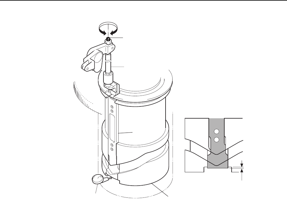
Adjustments >> Station Adjustme nts 7-28 MEC-CP842-1.0E 6 The vertical difference between the base of the slider and the cut out section in the cylindrical cam should be ±0.02 mm. If necessary , loosen the locknut …
Adjustments >> Station Adjustments
MEC-CP842-1.0E 7-27
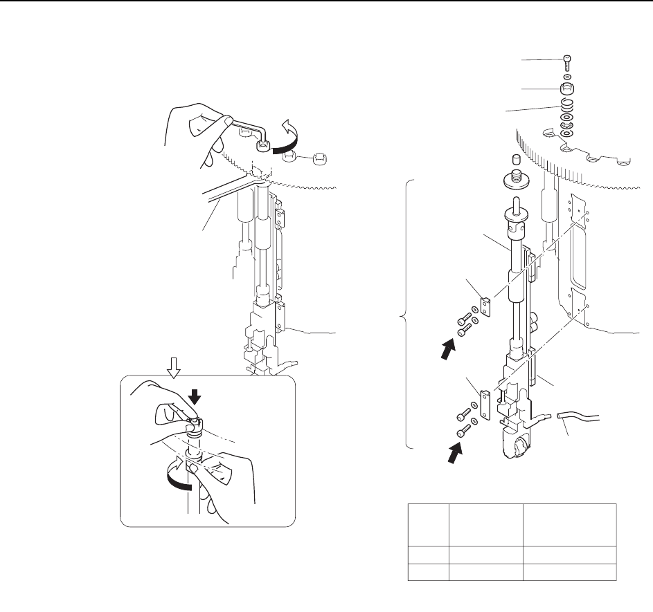
Caution:Do not disassemble nozzle shaft assemblies carelessly. Special equipment and skills are
required to remove and resemble a nozzle shaft. Such procedures should be attempted only
by maintenance staff who have attended training at Fuji and are equipped with the necessary
tools.
4 Move the turret slot for the removed nozzle shaft to between stations 8 and 9 at
0°, then turn on the solenoid (Y035 ST9 PLACE SOL ENGAGED).
5 With the cam angle at 0°, position the dial gauge as shown in the figure below.
Outer
shaft
Clamper
Wrench
( DCPJ0450 )
Clutch
Bolt
Spring
Linear guide
Vacuum hose
A
B
Part
Bolt
size
Torque
Nm ( Kgf/cm )
A
B
M4
M4
2 ( 20 )
2 ( 20 )
Clamper
C7SM4012a
Nozzle
shaft
assembly
Caution : Washers may move when the
bolt is loosened because of the
spring under the clutch.
Rotate the placing
head while holding
the bolt with finger.
Adjustments >> Station Adjustments
7-28 MEC-CP842-1.0E
6 The vertical difference between the base of the slider and the cut out section in
the cylindrical cam should be ±0.02 mm. If necessary, loosen the locknut in the
cambox and adjust the length of the rod.
7 Reattach the nozzle shaft assembly in the original location.
Using the clutch alignment jig, reverse the removal procedures to attach the
assembly.
Caution:The nozzle shaft assembly is exclusive to the CP-842E/842ME, and cannot be used on
other machine types, such as CP-733E, CP-743ME, or CP-743E.
Slider
Cam groove
Rod
Adjustment bolt
Dial gauge
±0.02 mm
C7SM4028a
Adjustments >> Station Adjustments
MEC-CP842-1.0E 7-29
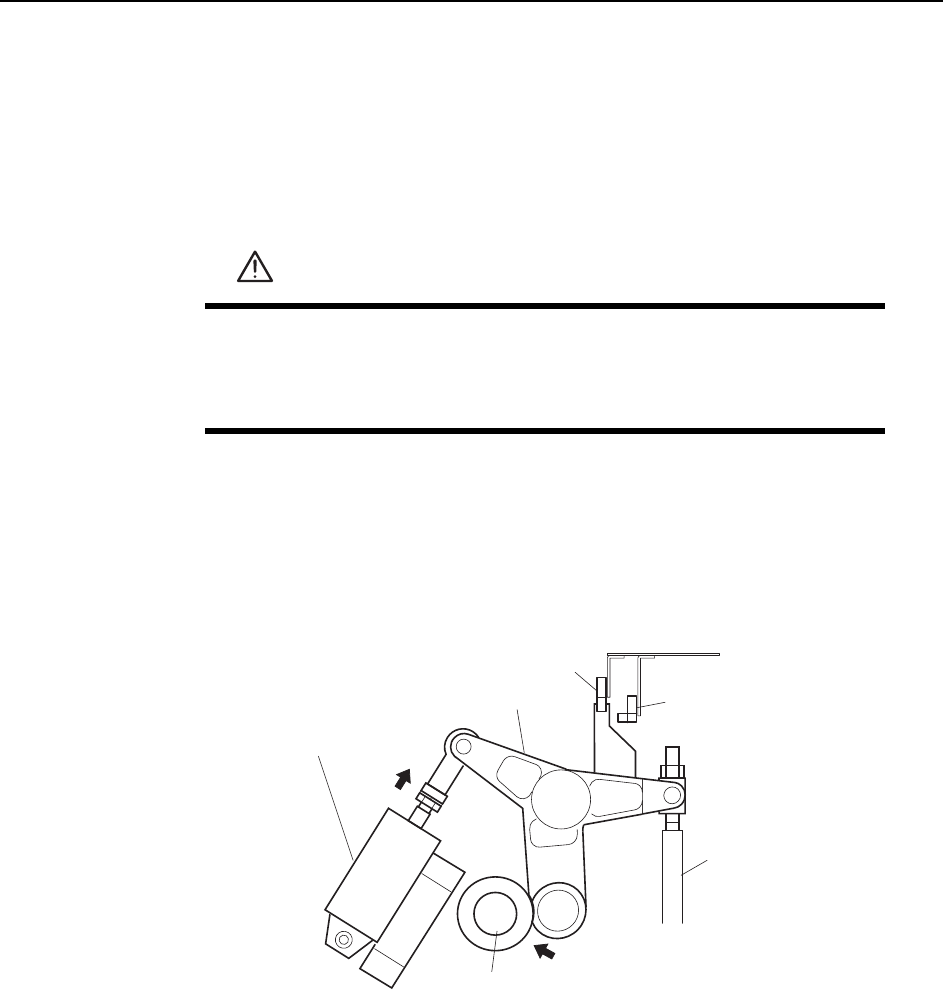
Adjusting the Nozzle UP Limit Sensors
The nozzle UP limit sensor that detects the up limit position of the nozzle UP/DOWN
rod at station 9 is mounted inside the cam box. Adjust the position of this sensor so
that it switches ON when the nozzle is at its UP limit position.
1 Press the EMERGENCY STOP button to take the 200V down to 100V.
2 Set the cam axis at 0°.
3 Activate the ST9 placing solenoid air cylinder (located in the cam box):
Execute the following I/O commands: [Maintenance] - [I/O Check] - [Standard I/
O] - [Y035 ST9 PLACE SOL ENGAGED] - [Output Signal ON]
The cam lever will then follow the cam.
WARNING
• Press EMERGENCY STOP before performing this procedure.
• Exercise extreme caution when working on the machine if the cam
is not at its origin (0 deg.). Spring recoil can rotate the cam inde-
pendently.
ST9 Place solenoid
air cylinder
Cam lever
Nozzle UP/DOWN rod
Cam axis
Cam lever follows
the cam.
C7SM4029a
Nozzle up limit sensor
Nozzle down limit sensor