MEC-CP842-1.0E.pdf - 第170页
Adjustments >> Station Adjustme nts 7-34 MEC-CP842-1.0E V alve Switching Lever Height Adjustment This adjustment should be pe rformed on the low valve shaf t after completing adjust- ments to the vertical movement …
Adjustments >> Station Adjustments
MEC-CP842-1.0E 7-33
7.1.10 Mechanical Valve Switching (ST9)
Point
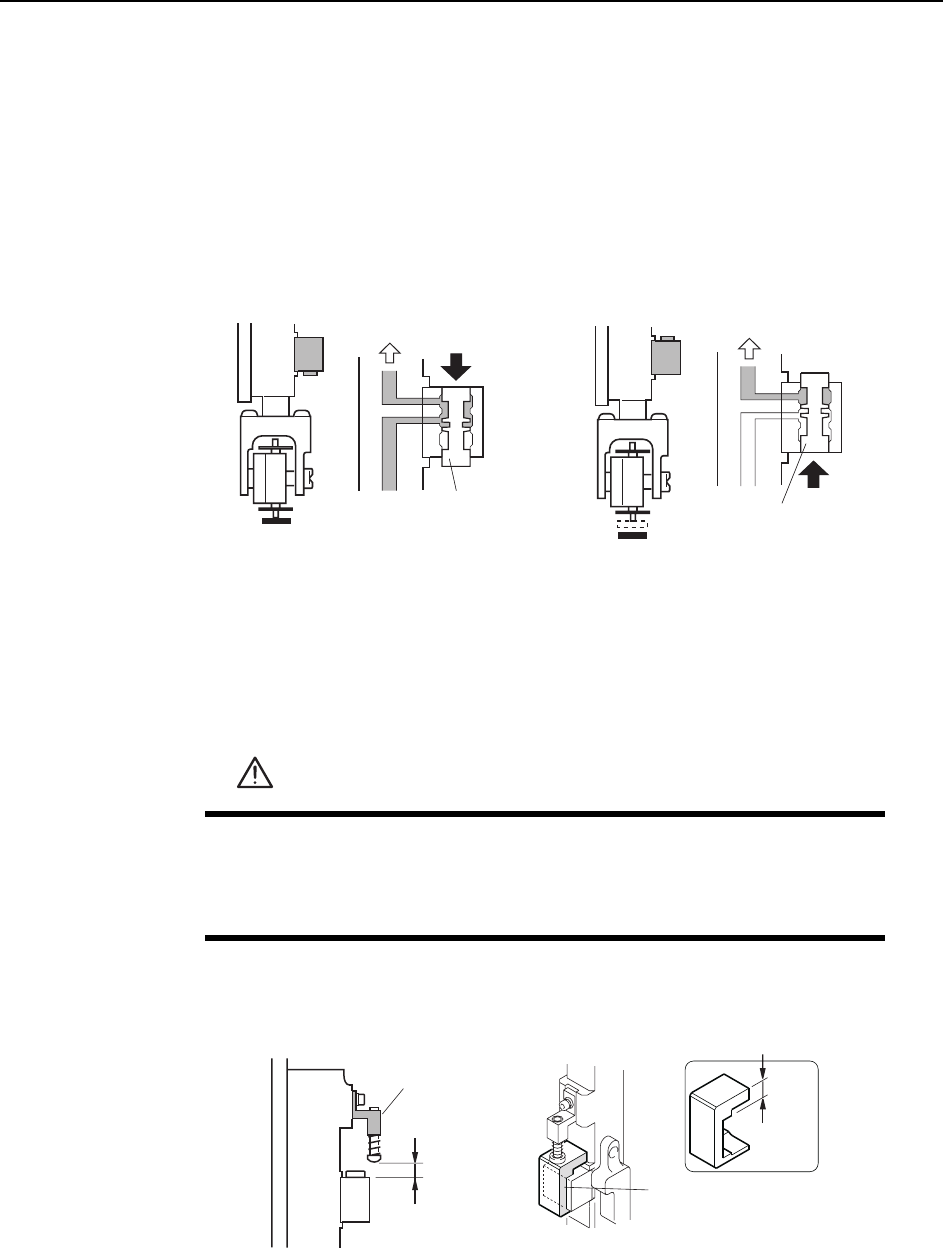
The nozzle vacuum switches from ON to OFF with the movement of the mechanical
valve at station 9. The vacuum cut is timed to allow part placement. Ensure that the
part is placed correctly on the production panel.
Checking the Position of the Pin Bracket
1 Press the EMERGENCY STOP button to turn off the 200V power, leaving only
the 100V power on.
2 Ensure that distance A (see figure below) is 8.9 mm for all heads. Use a special
jig (Z9827DGPJ029*) to check this distance.
WARNING
• Press EMERGENCY STOP before performing this procedure.
• Exercise extreme caution when working on the machine if the cam
is not at its origin (0 deg.). Spring recoil can rotate the cam inde-
pendently.
C7SM4036a
Vaccum ON Vaccum OFF
Vaccum
Vaccum
Spool
Spool
<Spool up><Spool down>
8.9 mm
2KPDTCEMGV
,KI
( Z9827DGPJ029*)
8.9 mm
C7SM4054Eb
A
Adjustments >> Station Adjustments
7-34 MEC-CP842-1.0E
Valve Switching Lever Height Adjustment
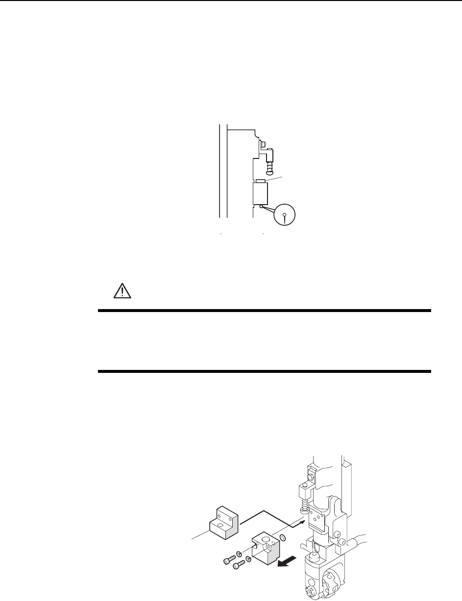
This adjustment should be performed on the low valve shaft after completing adjust-
ments to the vertical movement of the nozzle. (Refer to 7.1.9 “Nozzle Vertical Move-
ment During Placement” for details.) The low valve shaft can be identified by
measuring the lower surface of the mechanical valve spool on all shafts. Raise the
spools and measure with a dial gauge, as shown in the diagram below.
1 Press the EMERGENCY STOP button to take the 200V down to 100V.
2 Remove the mechanical valve block from the shaft that will be used for adjust-
ment.
Caution: There are two O-rings on the mechanical valve. Be careful to not drop these during removal
of the mechanical valve. Also, do not disassemble the mechanical valve if not necessary.
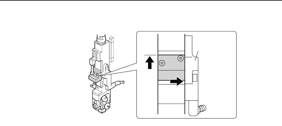
3 Position the centering jig (Z9827DGPJ032*) on the shaft in the mechanical valve position.
Lift the jig against the top ridge and push it to the right against the vacuum hose manifold
(black plastic).
WARNING
• Press EMERGENCY STOP before performing this procedure.
• Exercise extreme caution when working on the machine if the cam
is not at its origin (0 deg.). Spring recoil can rotate the cam inde-
pendently.
Spool
C7SM4055
C84PHD002E
Centering jig
( Z9827DGPJ032*)
Adjustments >> Station Adjustments
MEC-CP842-1.0E 7-35
4 Tighten the mounting bolts with a torque of 0.8 N.m (8Kgf.cm).
5 Set the cam angle to 0°, then activate the place solenoid (Y035 ST9 PLACE SOL
ENGAGED) at station 9 to work the lever.
6 Use the cam handle to rotate the cam to 190°. The pusher on the lever should align
smoothly with the centering jig.
C84PHD005E
/CPKHQNF