MEC-CP842-1.0E.pdf - 第177页
Adjustments >> Station Adjustments MEC-CP842-1.0E 7-41 1 Press the EMERGENCY STOP button to take the 200V down to 100 V . 2 Use the inching keys to move the Low valve head to ST12. 3 Remove the mechanical valve fro…
Adjustments >> Station Adjustments
7-40 MEC-CP842-1.0E
7.1.12 Mechanical Valve Switching (ST13)
Point
The station 13 mechanical valve is used to switch the nozzle vacuum off. The part is
released when the nozzle vacuum can no longer hold a part. Verify that parts that fail
vision processing are discarded at station 13.
Valve Switching Unit Position Adjustment
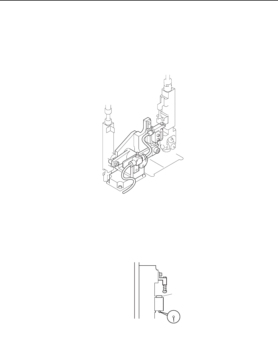
This adjustment should be performed on the low valve shaft after completing adjustments to the
vertical movement of the nozzle. (Refer to 7.1.9 “Nozzle Vertical Movement During Placement”
for details.) The low valve shaft can be identified by measuring the lower surface of the mechanical
valve spool on all shafts. Raise the spools and measure with a dial gauge, as shown in the diagram
below.
C7SM4041a
Spool
C7SM4055
Adjustments >> Station Adjustments
MEC-CP842-1.0E 7-41
1 Press the EMERGENCY STOP button to take the 200V down to 100V.
2 Use the inching keys to move the Low valve head to ST12.
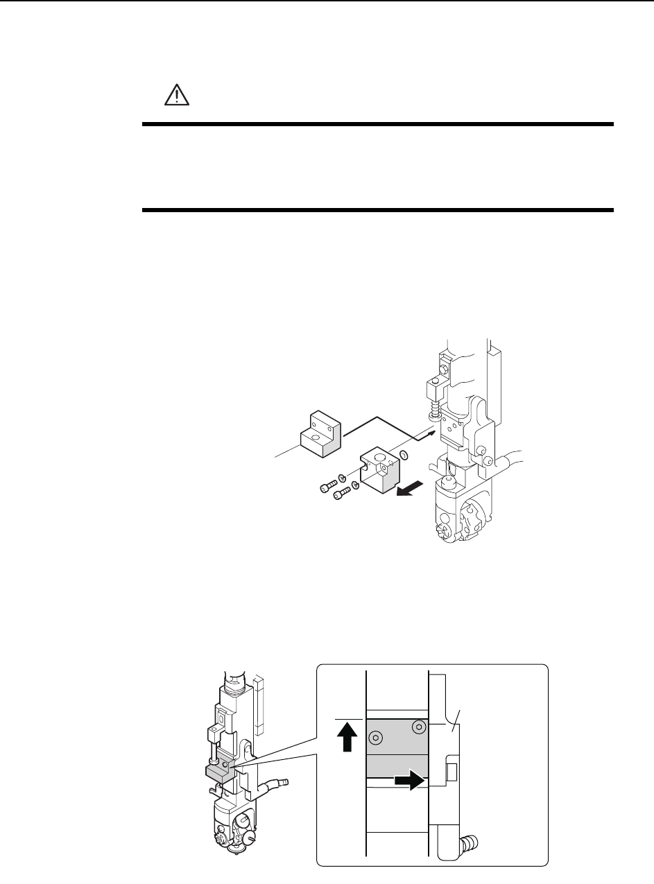
3 Remove the mechanical valve from the shaft that will be used for adjustment.
Caution: There are two O-rings on the mechanical valve. Be careful to not drop these during removal
of the mechanical valve. Also, do not disassemble the mechanical valve if not necessary.
4 Position the centering jig (Z9827DGPJ032*) on the shaft in the mechanical
valve position. Lift the jig against the top ridge and push it to the right against
the manifold (black plastic).
5 Tighten the mounting bolts with a torque of 0.8 N.m (8Kgf.cm).
6 Move the Low valve head to station 13.
WARNING
• Press EMERGENCY STOP before performing this procedure.
• Exercise extreme caution when working on the machine if the cam
is not at its origin (0 deg.). Spring recoil can rotate the cam inde-
pendently.
C84PHD002E
Centering jig
( Z9827DGPJ032*)
C84PHD005E
/CPKHQNF
Adjustments >> Station Adjustments
7-42 MEC-CP842-1.0E
7 Use the cam handle to rotate the cam to 192°. The pusher should align smoothly
with the centering jig. If not smooth, loosen the fixing bolts and adjust the posi-
tion of the mechanical valve switching unit.
8 Loosen the height adjustment fixing bolts and use the height adjustment bolt to
adjust the gap between the mechanical valve and pusher bracket. Insert a
0.2mm feeler gauge, and then adjust the gap between the step on the mechani-
cal valve jig and pusher bracket to 0.4mm. Tighten the fixing bolts.
Note: Do not touch the speed regulator.
The air-blow pressure is set to 7.0 ± 0.5 kPa (ST9: 15.0 ± 0.5 kPa). The user should not
change the setting unless a manometer is available for adjustment.
9 With the jig still on the shaft, move the shaft to ST10, 180°.
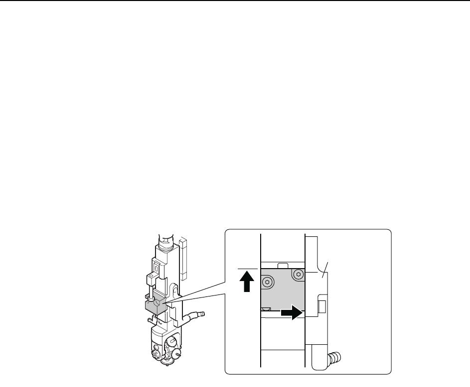
10 Remove the jig and return the mechanical valve and O-rings to the shaft. Lift
the mechanical valve against the top ridge and push it to the right against the
manifold (black plastic).
11 Tighten the mounting bolts with a torque of 0.8 N.m (8Kgf.cm).
C84PHD004E
/CPKHQNF