MEC-CP842-1.0E.pdf - 第178页
Adjustments >> Station Adjustme nts 7-42 MEC-CP842-1.0E 7 Use the cam handle to rotate the cam to 192°. The pusher should align smoothl y with the centering jig. If not smooth, l oosen the fixing bolts and adjust t…
Adjustments >> Station Adjustments
MEC-CP842-1.0E 7-41
1 Press the EMERGENCY STOP button to take the 200V down to 100V.
2 Use the inching keys to move the Low valve head to ST12.
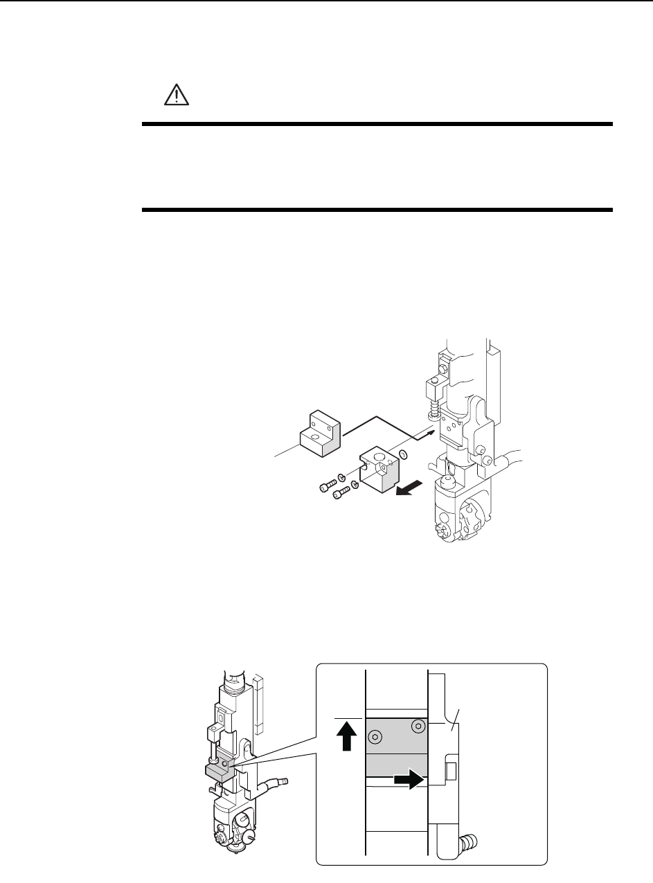
3 Remove the mechanical valve from the shaft that will be used for adjustment.
Caution: There are two O-rings on the mechanical valve. Be careful to not drop these during removal
of the mechanical valve. Also, do not disassemble the mechanical valve if not necessary.
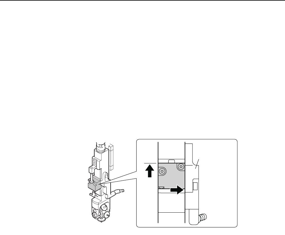
4 Position the centering jig (Z9827DGPJ032*) on the shaft in the mechanical
valve position. Lift the jig against the top ridge and push it to the right against
the manifold (black plastic).
5 Tighten the mounting bolts with a torque of 0.8 N.m (8Kgf.cm).
6 Move the Low valve head to station 13.
WARNING
• Press EMERGENCY STOP before performing this procedure.
• Exercise extreme caution when working on the machine if the cam
is not at its origin (0 deg.). Spring recoil can rotate the cam inde-
pendently.
C84PHD002E
Centering jig
( Z9827DGPJ032*)
C84PHD005E
/CPKHQNF
Adjustments >> Station Adjustments
7-42 MEC-CP842-1.0E
7 Use the cam handle to rotate the cam to 192°. The pusher should align smoothly
with the centering jig. If not smooth, loosen the fixing bolts and adjust the posi-
tion of the mechanical valve switching unit.
8 Loosen the height adjustment fixing bolts and use the height adjustment bolt to
adjust the gap between the mechanical valve and pusher bracket. Insert a
0.2mm feeler gauge, and then adjust the gap between the step on the mechani-
cal valve jig and pusher bracket to 0.4mm. Tighten the fixing bolts.
Note: Do not touch the speed regulator.
The air-blow pressure is set to 7.0 ± 0.5 kPa (ST9: 15.0 ± 0.5 kPa). The user should not
change the setting unless a manometer is available for adjustment.
9 With the jig still on the shaft, move the shaft to ST10, 180°.
10 Remove the jig and return the mechanical valve and O-rings to the shaft. Lift
the mechanical valve against the top ridge and push it to the right against the
manifold (black plastic).
11 Tighten the mounting bolts with a torque of 0.8 N.m (8Kgf.cm).
C84PHD004E
/CPKHQNF
Adjustments >> Station Adjustments
MEC-CP842-1.0E 7-43
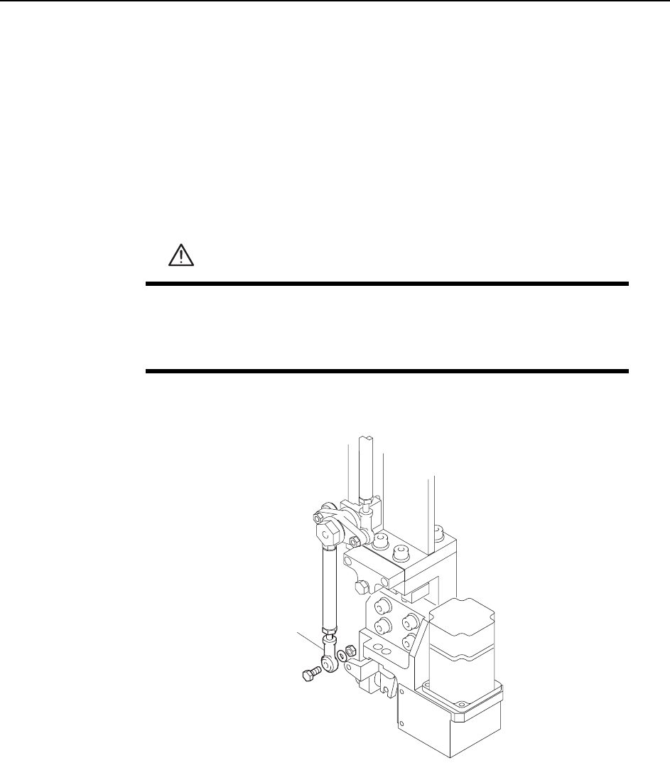
7.1.13 Nozzle Change Function (ST14)
Point
The station 14 nozzle changer selects the correct nozzle from the 6 that are available,
based on the part data.
Nozzle Change Clutch Position Adjustment
1 Press the EMERGENCY STOP button to take the 200V down to 100V.
2 Remove the rod end from the nozzle changer.
3 Remove the nozzle holders of the reference head and the adjacent heads.
4 Use the inching keys to move the reference head to ST14.
5 Use the cam handle to rotate the cam to 200°.
WARNING
• Press EMERGENCY STOP before performing this procedure.
• Exercise extreme caution when working on the machine if the cam
is not at its origin (0 deg.). Spring recoil can rotate the cam inde-
pendently.
C7SM4064
Rod end