MEC-CP842-1.0E.pdf - 第181页
Adjustments >> Station Adjustments MEC-CP842-1.0E 7-45 Nozzle Change S troke Adjustment 1 Press the EMERGENCY STOP button to take the 200V down to 100 V . 2 Position the cam at an angle of 0° and turn the ST14 sole…
Adjustments >> Station Adjustments
7-44 MEC-CP842-1.0E
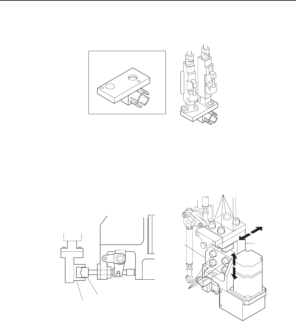
6 Attach the adjustment jig to the placing heads at ST14 and 15.
Note: Do not turn the cam with the jig attached to the placing heads; otherwise the heads might be
damaged.
7 Loosen the fixing bolts and adjust the clutch position so that the clutch fits
smoothly into the jig.
C7SM4063
ADCPJ8040
ST14
ST15
Adjustment jig
C7SM4065
Clutch
Bracket
Bracket
Fixing bolt
Fixing bolt
Adjustment jig
Adjustments >> Station Adjustments
MEC-CP842-1.0E 7-45
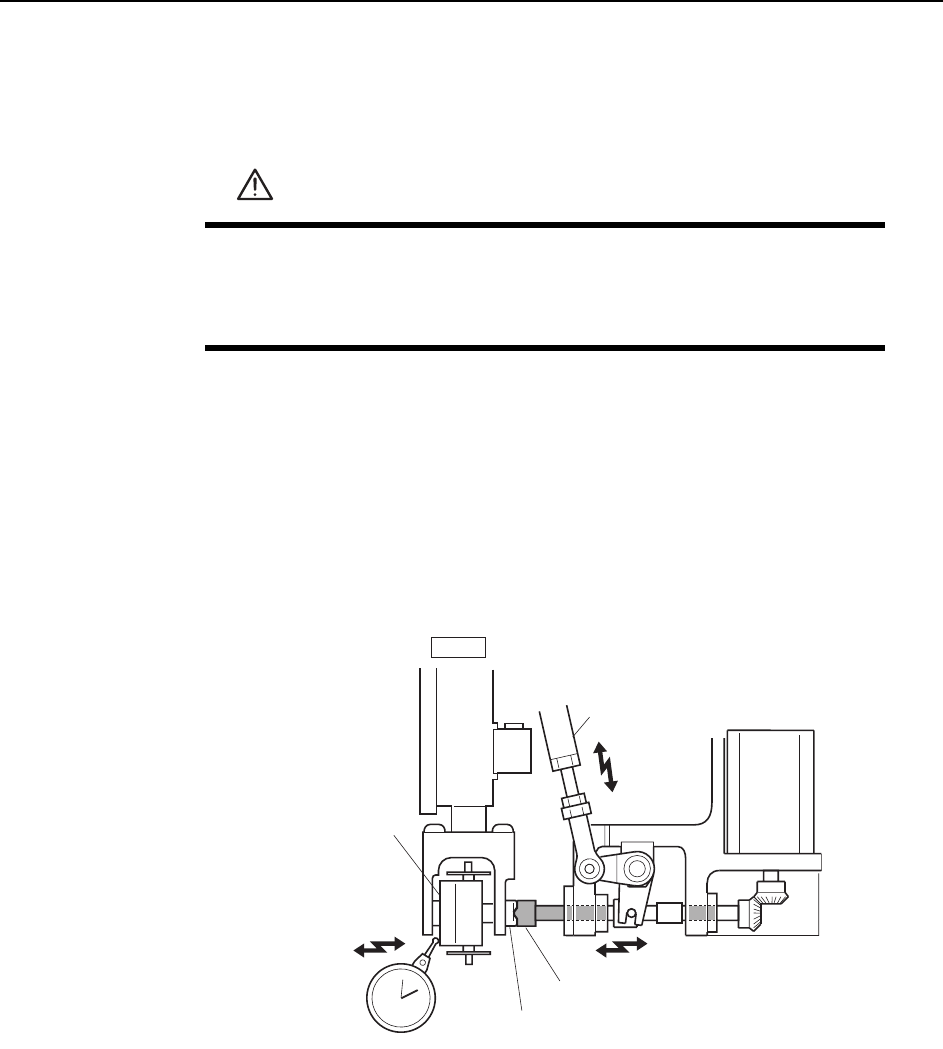
Nozzle Change Stroke Adjustment
1 Press the EMERGENCY STOP button to take the 200V down to 100V.
2 Position the cam at an angle of 0° and turn the ST14 solenoid to ON (Y037 ST14
NOZZLE CHANGE SOL ENGAGED) to activate the cam lever.
3 Zero the dial gauge when there is no contact between the clutches, and use the
cam handle to rotate the cam to 141°.
4 Verify that the nozzle change clutch is engaged with the holder clutch, and that
the rotary holder is pushed 0.01 to 0.05 mm as shown in the figure below.
5 If the stroke is out of range, adjust by turning the adjusting rod.
WARNING
• Press EMERGENCY STOP before performing this procedure.
• Exercise extreme caution when working on the machine if the cam
is not at its origin (0 deg.). Spring recoil can rotate the cam inde-
pendently.
Nozzle change clutch
Holder clutch
Adjustment rod
Rotary holder
ST14
0.01
~
0.05 mm
C7SM4048
Adjustments >> Station Adjustments
7-46 MEC-CP842-1.0E
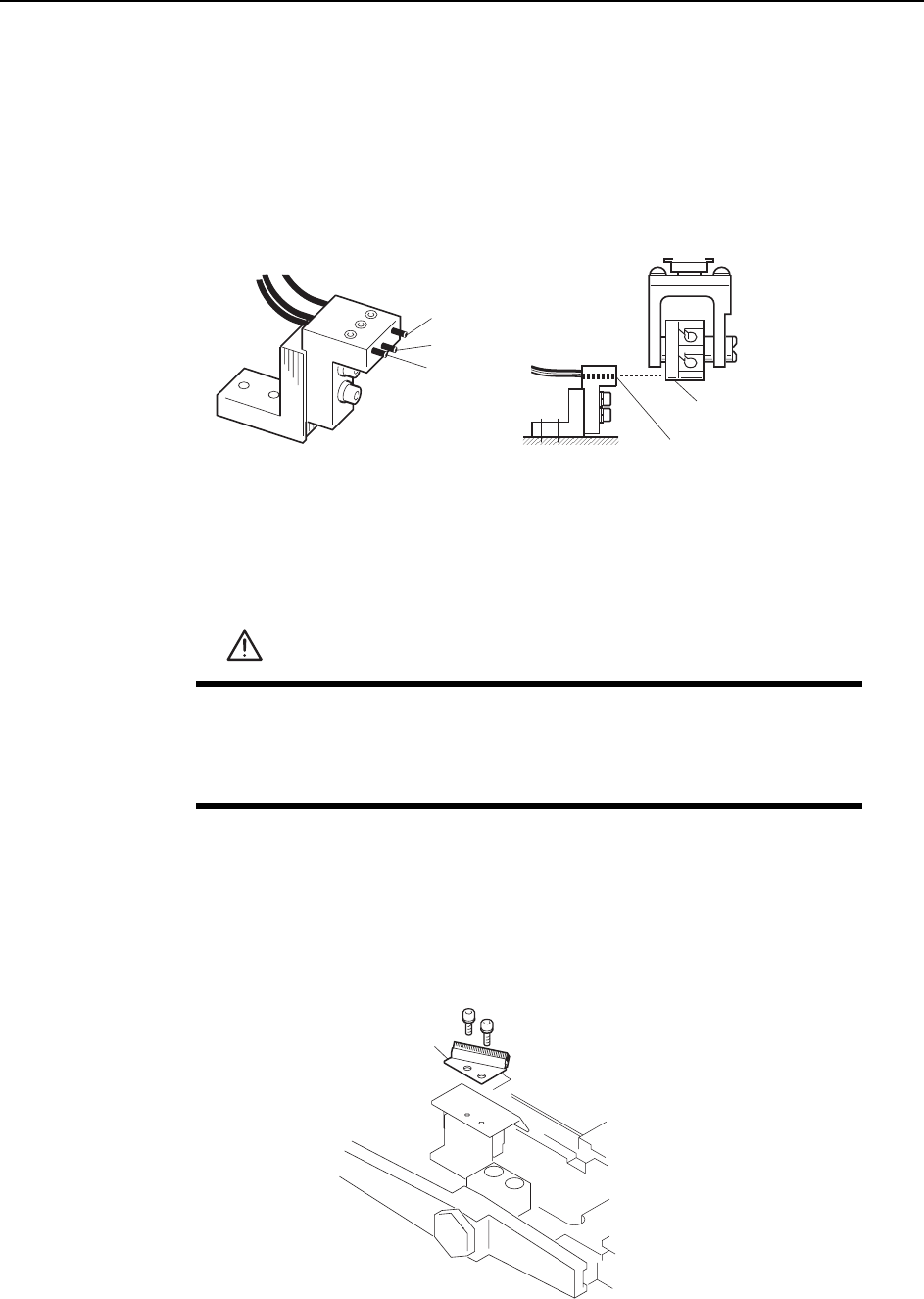
7.1.14 Nozzle Detection Sensor (ST15)
Point
Station 15 uses three nozzle detection sensors to detect which of the six nozzles (No. 1
~ 6) is down.
The following illustration shows the 3 sensors.
Sensor Position Adjustment
1 Press the EMERGENCY STOP button to take the 200V down to 100V.
2 Remove the nozzle holders of the reference head and the adjacent heads.
3 Use the inching keys to move the reference head to ST13.
4 Use the cam handle to rotate the cam to 200°.
5 Remove the reject parts brush.
WARNING
• Press EMERGENCY STOP before performing this procedure.
• Exercise extreme caution when working on the machine if the cam
is not at its origin (0 deg.). Spring recoil can rotate the cam inde-
pendently.
Dog
Sensor 3
Sensor
Sensor 2
Sensor 1
C7SM4043b
Reject parts brush
C7SM4059a