MEC-CP842-1.0E.pdf - 第182页
Adjustments >> Station Adjustme nts 7-46 MEC-CP842-1.0E 7.1.14 Nozzle Detection Sensor (ST15) Point Station 15 uses three nozzle detection sensor s to detect which of the six nozzles (No. 1 ~ 6) is down. The follow…
Adjustments >> Station Adjustments
MEC-CP842-1.0E 7-45
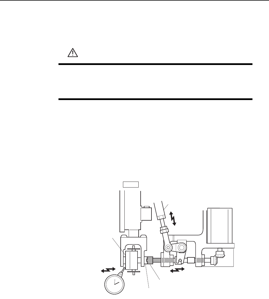
Nozzle Change Stroke Adjustment
1 Press the EMERGENCY STOP button to take the 200V down to 100V.
2 Position the cam at an angle of 0° and turn the ST14 solenoid to ON (Y037 ST14
NOZZLE CHANGE SOL ENGAGED) to activate the cam lever.
3 Zero the dial gauge when there is no contact between the clutches, and use the
cam handle to rotate the cam to 141°.
4 Verify that the nozzle change clutch is engaged with the holder clutch, and that
the rotary holder is pushed 0.01 to 0.05 mm as shown in the figure below.
5 If the stroke is out of range, adjust by turning the adjusting rod.
WARNING
• Press EMERGENCY STOP before performing this procedure.
• Exercise extreme caution when working on the machine if the cam
is not at its origin (0 deg.). Spring recoil can rotate the cam inde-
pendently.
Nozzle change clutch
Holder clutch
Adjustment rod
Rotary holder
ST14
0.01
~
0.05 mm
C7SM4048
Adjustments >> Station Adjustments
7-46 MEC-CP842-1.0E
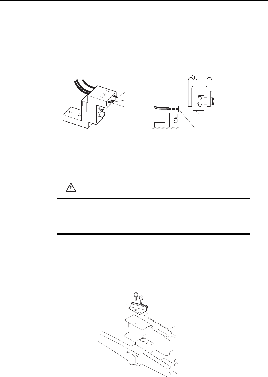
7.1.14 Nozzle Detection Sensor (ST15)
Point
Station 15 uses three nozzle detection sensors to detect which of the six nozzles (No. 1
~ 6) is down.
The following illustration shows the 3 sensors.
Sensor Position Adjustment
1 Press the EMERGENCY STOP button to take the 200V down to 100V.
2 Remove the nozzle holders of the reference head and the adjacent heads.
3 Use the inching keys to move the reference head to ST13.
4 Use the cam handle to rotate the cam to 200°.
5 Remove the reject parts brush.
WARNING
• Press EMERGENCY STOP before performing this procedure.
• Exercise extreme caution when working on the machine if the cam
is not at its origin (0 deg.). Spring recoil can rotate the cam inde-
pendently.
Dog
Sensor 3
Sensor
Sensor 2
Sensor 1
C7SM4043b
Reject parts brush
C7SM4059a
Adjustments >> Station Adjustments
MEC-CP842-1.0E 7-47
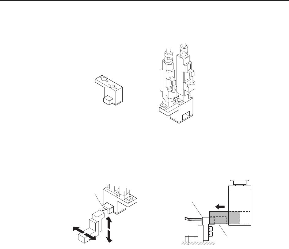
6 Attach the adjustment jig (for ST15) to the placing heads at ST15 and 16.
Note: Do not turn the cam with the jig attached to the placing heads; otherwise the heads might be
damaged.
7 Adjust the sensor bracket position so that the jig smoothly slides over the sensor
bracket.
C7SM4062
ST15
ST16
ST15
A
djustment jig
ADGPJ8050
Jig block
Jig block
Sensor bracket
C7SM4061