MEC-CP842-1.0E.pdf - 第185页
Adjustments >> Station Adjustments MEC-CP842-1.0E 7-49 4 Ensure that the sensors display fo r the other nozzles as shown below . Nozzle 1 Nozzle 2 Nozzle 3 Nozzle 4 Nozzle 5 Nozzle 6 Sensor 1 ON OFF OFF ON OFF ON S…
Adjustments >> Station Adjustments
7-48 MEC-CP842-1.0E
Checking the Sensor Reaction
1 Press the EMERGENCY STOP button to take the 200V down to 100V.
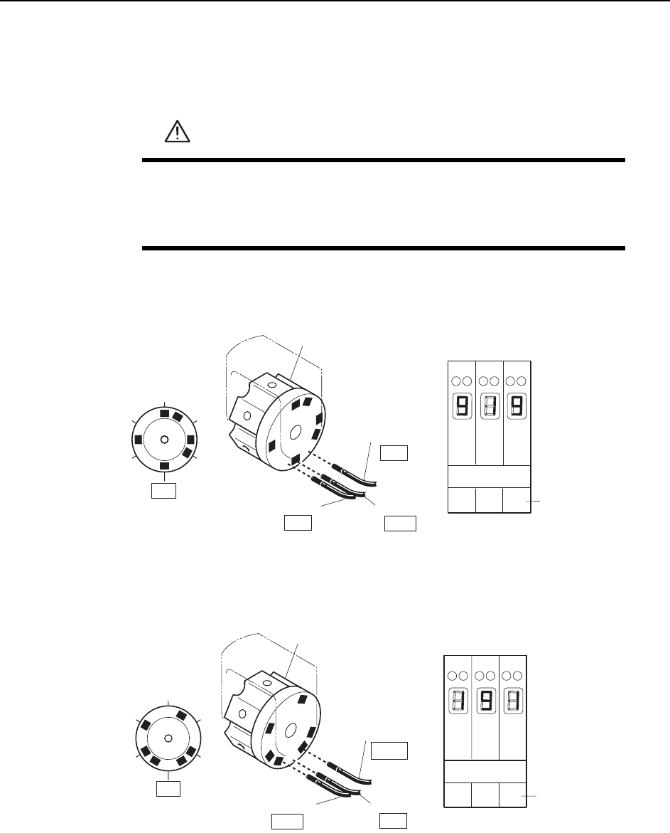
2 Manually rotate the rotary holder to select nozzle No. 6. At this time, the sensor
reactions should be the same as shown below.
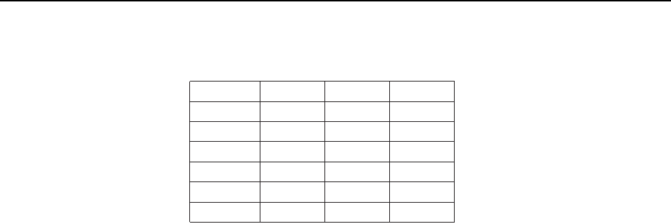
3 Rotate the rotary holder to select nozzle No. 2. At this time, the sensor reactions
should be the same as shown below.
WARNING
• Press EMERGENCY STOP before performing this procedure.
• Exercise extreme caution when working on the machine if the cam
is not at its origin (0 deg.). Spring recoil can rotate the cam inde-
pendently.
123
Amp front view
Sensor 1
Nozzle
Sensor 2
OFF
Sensor 3
ON
Rotary holder
ON
1
2
3
4
5
6
Sensor No.
Digital display
0, 1 = Sensor OFF
8, 9 = Sensor ON
13ST
C7SM4044a
Sensor 1
Nozzle
Sensor 2
OFF
Sensor 3
Rotary holder
ON
C7SM4045a
1
2
3
4
5
6
OFF
123
Amp front view
Sensor No.
Digital display
0, 1 = Sensor OFF
8, 9 = Sensor ON
13ST
Adjustments >> Station Adjustments
MEC-CP842-1.0E 7-49
4 Ensure that the sensors display for the other nozzles as shown below.
Nozzle 1
Nozzle 2
Nozzle 3
Nozzle 4
Nozzle 5
Nozzle 6
Sensor 1
ON
OFF
OFF
ON
OFF
ON
Sensor 2
OFF
ON
OFF
ON
ON
OFF
Sensor 3
OFF
OFF
ON
OFF
ON
ON
T001
Digital display
0,1 = Sensor OFF
8,9 = Sensor ON
Adjustments >> Station Adjustments
7-50 MEC-CP842-1.0E
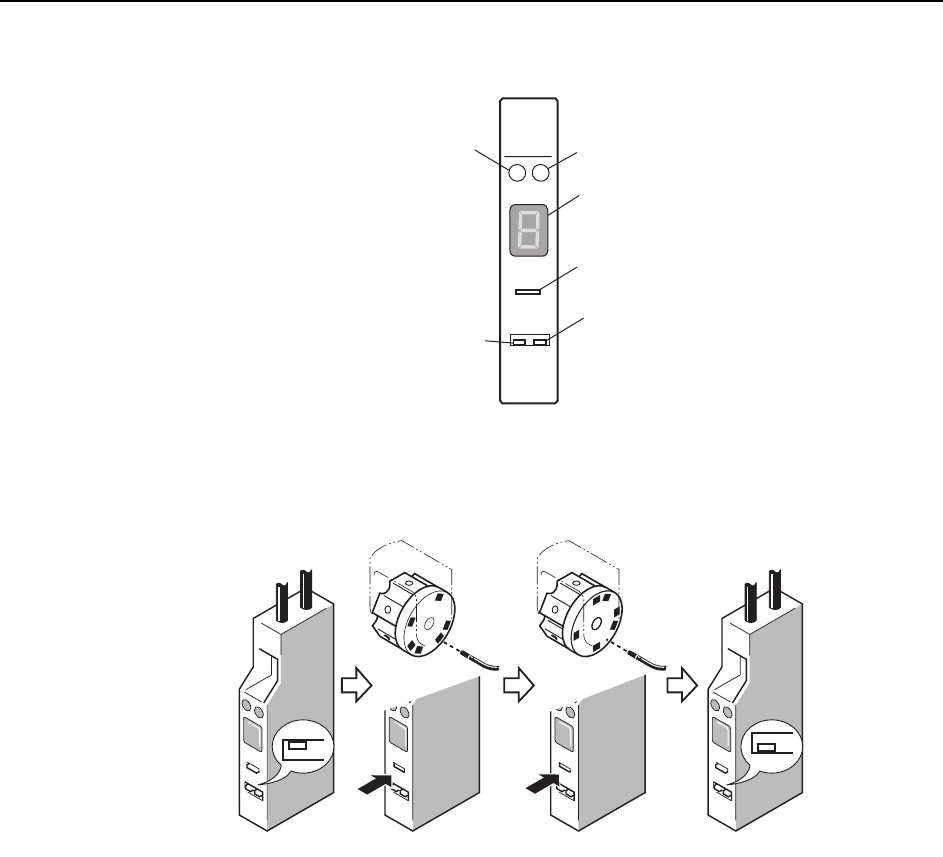
Sensor Sensitivity Adjustment
Remove the cover of the amplifier and follow the adjustment procedure below.
Note: Be careful not to drop the cover inside the machine.
Set the L-ON/D-ON switch to L-ON for the nozzle detection sensor.
1 Move the amplifier's mode change switch to the "SET" position.
2 Rotate the nozzle holder until the sensor light beam is adjacent to a dark part of
the dog and press "TUNING".
3 Rotate the nozzle holder until the sensor light beam is adjacent to a metal part
of the dog and press "TUNING".
4 Return the amplifier's mode changing switch to the "RUN" position.
At this time the sensitivity of the sensor can be checked on the digital display.
Digital display:
0 ~ 1: Stable interruption range
8 ~ 9: Stable light input range
If the display is within the stable range, setting is complete.
5 If the display is not within the stable range, check the items below and make
the necessary adjustments.
• Check the connections between the amplifier and the fiberoptic cable.
• Check the position of the sensor.
S
O
DELAY
TUNING
SET D-ON
RUN L-ON
HPY-T1
Green LED
Red LED
Digital display
Tuner
L-ON/D-ON
switch
Mode changing
switch
C7SM4046
SET
RUN
C7SM4047a
(1) (2) (3) (4)