MEC-CP842-1.0E.pdf - 第188页
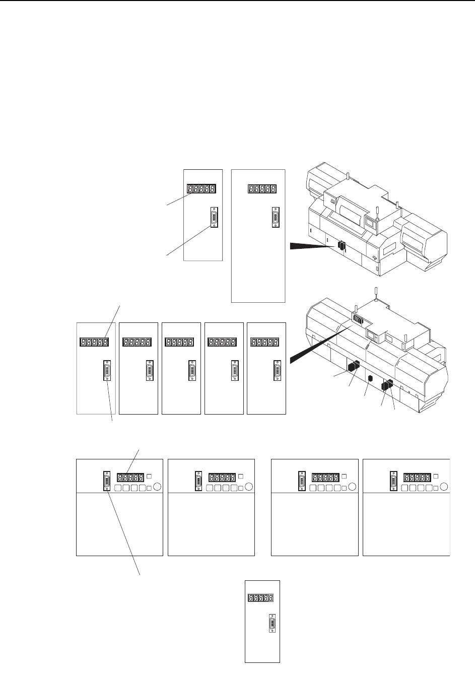
Adjustments >> Servo Amplifier Adjustments 7-52 MEC-CP842-1.0E Servo amplifier EQPPGEVQT CN3 Y-axis Z-axis LED panel <CP-842ME> 5GTXQCORNKHKGTEQPPGEVQT CN3 5GTXQCORNKHKGTEQPPGEVQT CN3 NZ-axis …
Adjustments >> Servo Amplifier Adjustments
MEC-CP842-1.0E 7-51
7.2 Servo Amplifier Adjustments
Required Tools
Required Tools:1 Digital Operator
7.2.1 Servo amplifier parameters
1 Connect the Digital Operator cable to the servo amplifier to be adjusted (CN-3
connector).
5GTXQCORNKHKGT
EQPPGEVQTCN3
CP-842E
Y-axisZ-axis
LED panel
<CP-842E>
C7SM4071Ea
5GTXQCORNKHKGTEQPPGEVQTCN3
5GTXQCORNKHKGTEQPPGEVQTCN3
NZ-axisPǰ-axisFǰ-axisRǰ-axis NC -axis
LED panel
LED panel
(1) (2) (3) (4)
D1-axis D2-axis Cam-axisX-axis
(1)
(2)
(4)
(3)
(5)
NY-axis
(5)
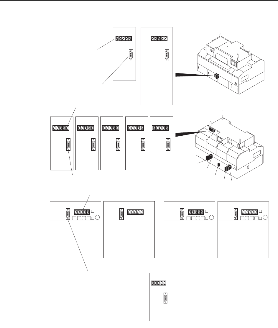
Adjustments >> Servo Amplifier Adjustments
7-52 MEC-CP842-1.0E
Servo amplifier
EQPPGEVQTCN3
Y-axisZ-axis
LED panel
<CP-842ME>
5GTXQCORNKHKGTEQPPGEVQTCN3
5GTXQCORNKHKGTEQPPGEVQTCN3
NZ-axisPǰ-axisFǰ-axisRǰ-axis NC-axis
LED panel
LED panel
(1)
(2)
(4)
(3)
C7SM4070Ea
(1) (3)(2) (4)
D1-axis D2-axis
Cam-axisX-axis
C
P-842M
E
(5)
(5)
NY-axis
Adjustments >> Servo Amplifier Adjustments
MEC-CP842-1.0E 7-53
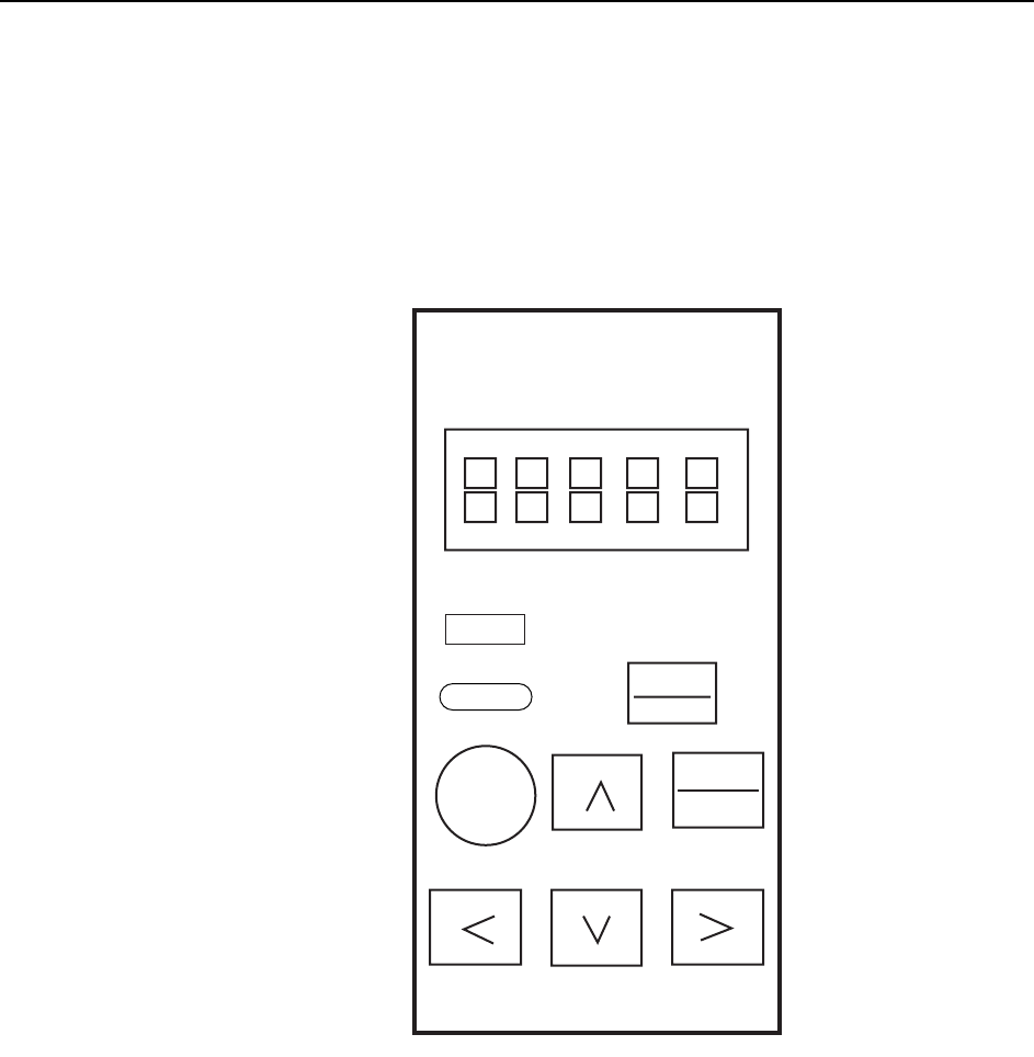
2 Press the [DSPL/SET] button on the Digital Operator until “PN-00” is displayed
by the LED indicator.
3 The parameter type can be changed by pressing the Up or Down arrow key.
4 When the desired parameter is displayed, press the [DATA/ENTER] button and
check the current setting.
Note: Contact Fuji if any of the displayed parameters differ from those indicated in the servo param-
eter sheet. Do not change the parameter settings unless otherwise instructed.
5 After confirming the parameter setting, press the [DSPL/SET] button to return
to the “PN-XX” display. Repeat steps 3 to 5 to check all the parameters.
DSPL
SET
JOG
SVON
DATA
ENTER
Yaskawa
QP3M4008Ea
Servo Pack Digital
Operator
Jusp-0p02A
Reset
Reset
Alarm