MEC-CP842-1.0E.pdf - 第218页
Setup >> Leveling t he Machine 9-2 MEC-CP842-1.0E Procedure 1 Position the leveling sheets or the leveli ng blocks as shown in the figure below . 2 Set spirit levels on a base surface of the mach ine (laterally and…
Setup >> Leveling the Machine
MEC-CP842-1.0E 9-1
9. Setup
9.1 Leveling the Machine
Point
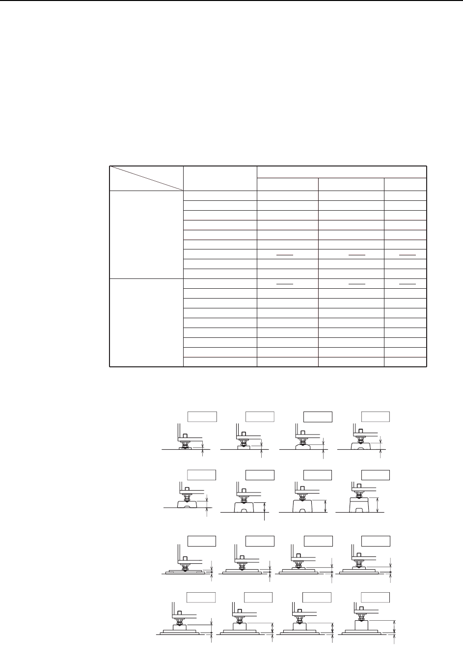
The machine should be set in position on leveling sheets or blocks. The appropriate
leveling sheets and blocks differ depending on the panel conveyance height, and the
use of anti-vibration pads. Refer to the table below.
C746M6T01
Board conveyance
height
Anti-vibration pads
not used.
Anti-vibration pads
used.
Leveling sheet / block
900
Units (mm)
912
920
930
935
950
962
965
980
900
912
920
930
935
950
962
965
980
12
22
30
40
40
60
75
90
24 *
28 *
40 *
44 *
60 *
71 *
71 *
87 *
DCAB0370
DCAB0380
BB43880
GGA8060
GGA8060
GGA8030
GGA8040
BB42950
DCAB0390
GXA2071
DCAB0400
WAB0601
GXA2121
DCAB0410
DCAB0410
DCAB0420
Leveling sheet
HeightDrawing No. Name
Leveling sheet
Leveling sheet
Leveling sheet
Leveling sheet
Leveling sheet
Leveling sheet
Leveling sheet
Leveling sheet
Leveling sheet
Leveling block
Leveling block
Leveling block
Leveling block
Leveling block
Leveling block
* : Includes height of anti-vibration pads (12mm).
C746M6001
H=935H=920
H=920
H=930H=912
H=930H=912
H: Board conveyance height Units (mm)
H=900
A
nti-vibration pads
used.
Anti-vibration pads
not used.
32
28
16
12
40
30
22
12
12
12
12
12
H=980H=965H=950
90
75
60
H=980H=965H=950 H=962
48
59
75
59
12
12
12
12
H=935
40
Setup >> Leveling the Machine
9-2 MEC-CP842-1.0E
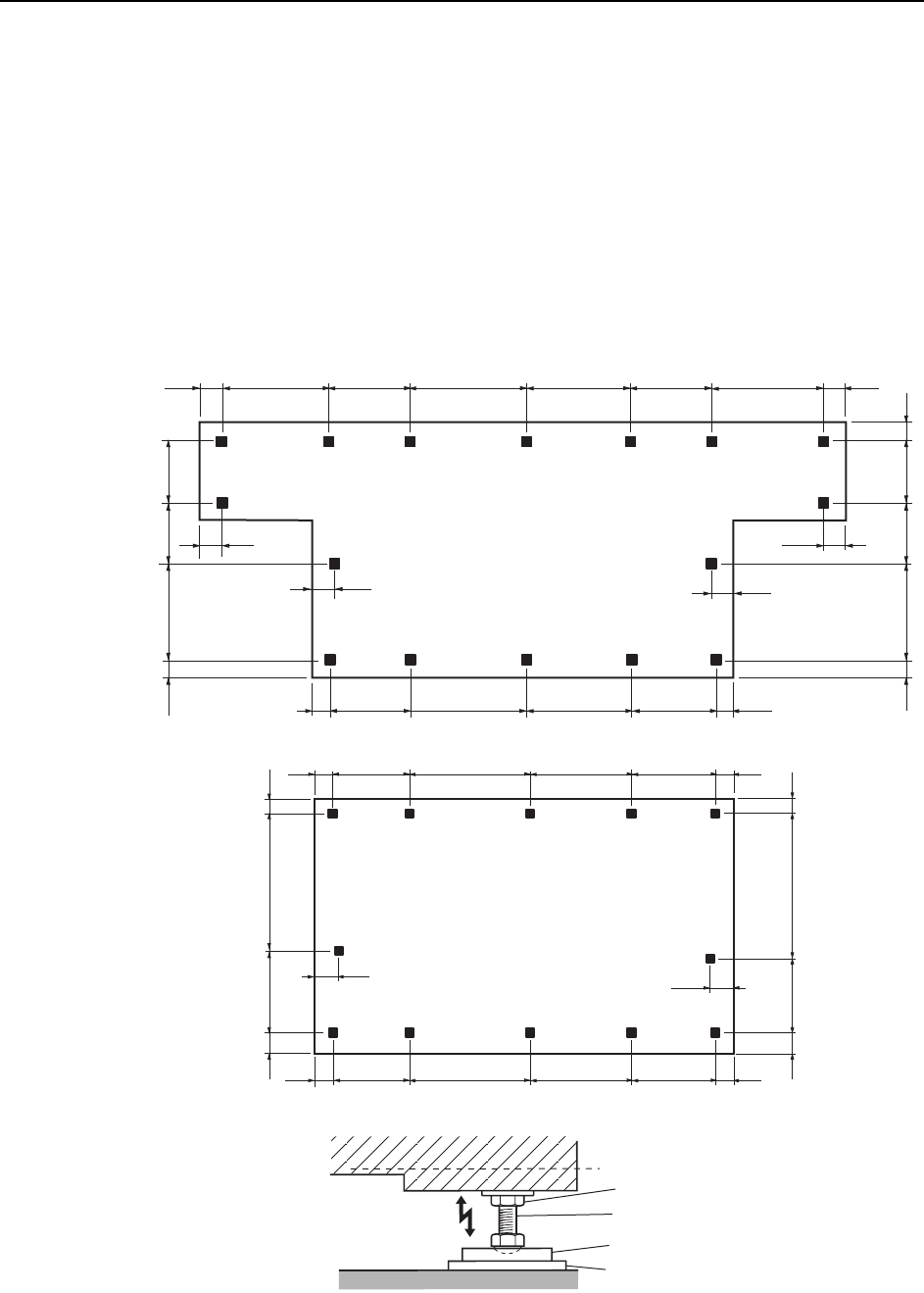
Procedure
1 Position the leveling sheets or the leveling blocks as shown in the figure below.
2 Set spirit levels on a base surface of the machine (laterally and vertically).
3 Use the leveling bolts to adjust the height.
4 After verifying that the panel conveyance height and the leveling accuracy are
correct, tighten the lock nuts on the leveling bolts. Level will change when the
lock nuts are tightened, so double-check the level after tightening.
Note: If the lock nuts are not tightened sufficiently, vibration may result in a drop in placement accu-
racy.
C746M6002
125
125
125
125
(mm)
538696778
518
125
730 518 778 696 538 730
125
150
150
100 549 510 455 100
100 593 466
455
<CP-842ME>
<CP-842E>
125
125
(mm)
538696778
518
125
125538696778518
150
150
549 965 100
100
593 921 100
100
Lock nut
Leveling bolt
Leveling sheet
Anti-vibration pad
Setup >> Connecting the Air Supply
MEC-CP842-1.0E 9-3
9.2 Connecting the Air Supply
Point
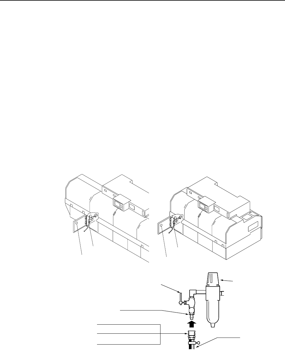
Connect the air hose to the machine, and adjust the regulator to the prescribed air
pressure.
Procedure
1 Connect the air hose to the machine’s air inlet located on the front of the
machine.
2 Raise the filter regulator knob to release the lock.
3 Turn the handle to adjust the air pressure until the gauge reads 0.5 MPa (5kgf/
cm2).
Note: A digital pressure gauge is attached to the rear cover.
4 Press the filter regulator knob down to engage the lock.
Note: The air hose is not supplied with the machine.
<CP-842E>
0.5MPa (5kgf/cm )
2
C746M6003
<CP-842ME>
Air inlet
Digital pressure gauge
Air inlet
Digital pressure gauge
30SH ( for 3/8" hose)
20SH ( for 1/4" hose)
40SH ( for 1/2" hose)
Socket
Hose
20PM Plug
Handle
Knob