2500_Users_Manual - 第100页
Task s and Ki ts ProM aster 25 00 User Manua l 3-25 Serializ ation Parameters TaskLink s upplies a sample ESP called “ seriali z.exe ” to use as a tem plate for developing your program. The source code (named “ serializ …
Tasks and Kits
3-24 ProMaster 2500 User Manual
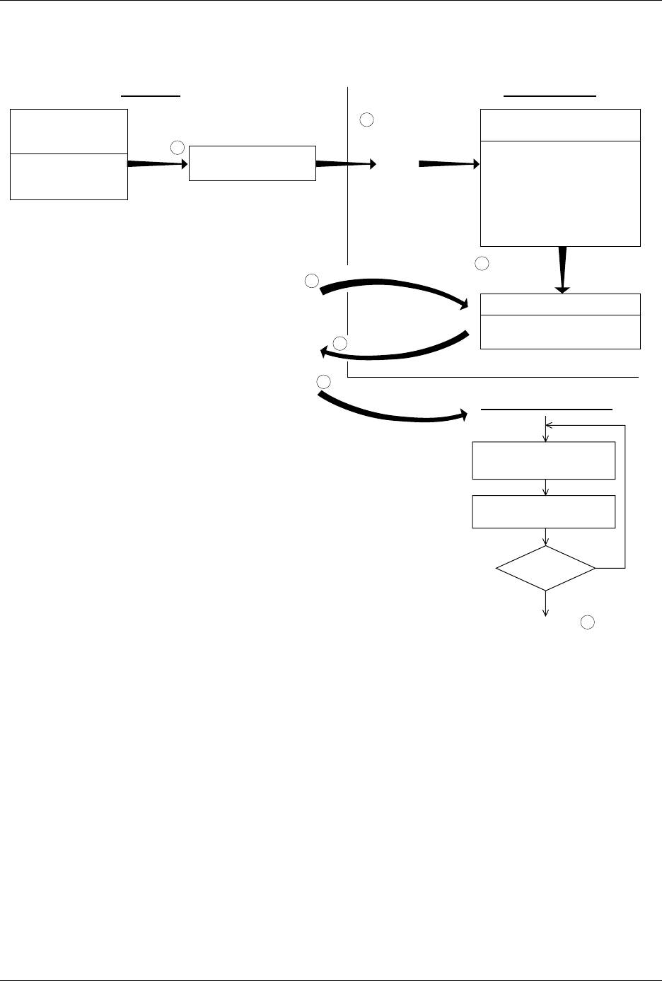
Figure 3-16
The Serialization Process
TASKLINK PC HARD DRIVE
"PROCESS DEVICES"
Task runs
EXTERNAL SERIALIZATION
PROGRAM (ESP)
Written by user.
Generates a serial number.
Creates an ASCII file called
"serial.dat."
"serializ.exe" is a sample of
a basic external serialization
program.
Calls "ESP" and
passes parameters
-a
-f
-i
-l
-h
-o
-s
-t
"SERIAL.DAT" (ASCII FILE)
Eight-line file containing
serial number
ESP creates
"serial.dat"
T
a
s
k
L
i
n
k
l
o
o
k
s
f
o
r
"
s
e
r
i
a
l
.
d
a
t
"
R
e
a
d
s
"
s
e
r
i
a
l
.
d
a
t
"
Data file created
by "ESP" to handler
1920-2
SERIALIZATION
PARAMETERS
DIALOG BOX
Operator provides
TaskLink with "ESP"
program name.
1
2
3
4
5
Next blank device placed
in programming module
Program device
Device
pass?
Return to step .1
Yes
No
D
o
w
n
l
o
a
d
s
s
e
r
i
a
l
n
u
m
b
e
r
6
PROMASTER HANDLER

Tasks and Kits
ProMaster 2500 User Manual 3-25
Serialization Parameters
TaskLink supplies a sample ESP called “
serializ.exe
” to use as a template
for developing your program. The source code (named “
serializ.c
”) for
this program is included with TaskLink. Figure 3-15 shows the
Serialization Parameters dialog box. To use
serializ.exe
to place a serial
number in programmer RAM, set the parameters as follows:
Note: For compatibility with external serialization programs you may have
written for HandlerLink, select Memory Buffer for the Serialization
Method.
External Serialization
Program (ESP) Serializ.exe
is used to illustrate passing parameters to the ESP. This is a
simple program that can be used to generate a serial number for each
device that programs successfully. It directs the labeler to print a label
with that serial number.
Some of the parameter options that you can pass to the external software
program on the Program command line include:
• Serial number’s address in the device
• Serial number’s format (decimal, hex, binary)
• Length (number of bytes)
• Byte order of high and low bytes
• Value used to increment each serial number
• Format of the serial number printed on the label (binary,
ASCII decimal, or ASCII hexadecimal)
Parameter Setting
Serialization Method File
RAM Serialization On
Program
serializ.exe
*
* Include any command line parameters you want, as described in the next section.
Edit Starting Number No
Keep Next Number Yes
Next Serial Number starting_serial_number

Tasks and Kits
3-26 ProMaster 2500 User Manual
The following example gives these sample values for the parameters: a
10-character ASCII hexadecimal serial number at address 12345
(hexadecimal), increase the serial number by an increment of 2 for each
device programmed, and print each serial number on the device label (in
hexadecimal). The Program entry field in the
Setup/Serialization
dialog
box might look like this:
serializ.exe
–l10 –fh –a12345 –i2 –h
Parameter Description
–a
Address of serial number.
Defines the device address (hexadecimal value) where the
serial number will be programmed in the device. For
example, –a12345 places the serial number at hexadecimal
address 12345.
Default
: Zero (–a0)
–f
Format of serial number.
Defines the format of the serial number in the device.
These three formats are supported:
–fb = Binary
–fd = ASCII decimal
–fh = ASCII hexadecimal
Default:
Binary (–fb)
–i
Serial number increment.
Defines the decimal value to be used to increment the
serial number after each successfully programmed
device. For example, –i2 increases the serial number by 2
for each device programmed.
Default:
1 (–i1)
-l
Length of serial number.
Defines the number of bytes the serial number occupies in
the device. The following settings are supported.
1 through 4 Binary
1 through 8 ASCII hexadecimal
1 through 10 ASCII decimal
Default:
2 (–l2)
–m
Pure Set gang serialization mode.
Serial numbers are generated one device size apart in
programmer RAM instead of in a single block just beyond
the fixed data in RAM. TaskLink then programs devices
in a single-pass operation with a set size equal to the
number of installed sockets.
–o
Byte order of serial number.
Serial numbers are placed in RAM with the most
significant byte (MSB) or the least significant byte (LSB) at
the first (lower) RAM address. This setting applies to
binary and ASCII formats. The settings are
–om = MSB at first RAM address (Motorola-style)
–oi = LSB at first RAM address (Intel-style)
Default:
MSB at first RAM address (–om)