2500_Users_Manual - 第122页
Operation 4-8 ProMa ster 25 00 U ser Ma nual • Is a new label type need ed? • If you changed label type, d id you calibrate the labels? • Have you inserted the input tubes wit h the correct orientation for device pin 1? …

Operation
ProMaster 2500 User Manual 4-7
If you forget your password, the system administrator will have to
remove your name from the list of users and then re-enter it. This allows
you to start again with the default password.
Checking TaskLink
Communication with the
2500
To confirm that communication between TaskLink and the 2500’s
programming electronics has been established, press
C
TRL
+
F1
on the PC
keyboard.
Note: The 2500’s power-up self-test takes approximately two minutes to
complete. During this time, TaskLink will not be able to establish
communication with the 2500.
If a successful communication link is established, the PC screen displays a
green box that contains the following message:
Contact with programmer established
.
If there is a problem, the PC screen displays a red box that contains the
following message:
Attempting to contact programmer...
and the PC screen displays several suggested troubleshooting actions to
take to investigate the problem.
To confirm that communication between TaskLink and the Remote port
on the 2500 has been established, press
C
TRL
+
F2
on the PC keyboard.
If a successful communication link is established, the PC screen displays a
green box that contains the following message:
Contact with handler established
.
If there is a problem, the PC screen displays a red box that contains this
message:
Attempting to contact handler...
and the PC screen displays several suggested troubleshooting actions to
take to investigate the problem.
Reconfiguring the
System for a New
Device
This section describes the various steps you must check before you start a
Task using a new device type. The new part may have a different size or
be a different package type (such as DIP, SOIC, or PLCC). Each time you
change devices types between Tasks, answer the following questions and
reconfigure the 2500 if required before starting the new Task:
• Does the device need a different programming module?
• Does the programming module need to be reconfigured?
• Does the track width need to be adjusted?
• Does the track air need to be adjusted?
• Is the correct chuck installed on the beam?
Operation
4-8 ProMaster 2500 User Manual
• Is a new label type needed?
• If you changed label type, did you calibrate the labels?
• Have you inserted the input tubes with the correct orientation for
device pin 1?
Descriptions for each of these adjustments are presented in the same
order in the following sections.
Configuring the
Programming
Module
To support the widest variety of devices, the 2500’s programming
modules are jumper configurable so they can support faster, higher
density devices. With higher speed, some devices are more sensitive to
electronic noise levels on signal and programming pins. The
programming modules have configuration blocks that hold the
decoupling capacitors required to take care of possible noise on the
device pins.
To program most devices, you use the module configuration that
supports power and ground pins at their traditional locations. You may
occasionally need to reconfigure the programming module to program
devices that have additional power and ground pins or power and
ground in different locations.
When you reconfigure a module, you place configuration blocks in
locations required by the device. This puts the necessary decoupling
capacitors as close as possible to the device pins where they are needed.
In addition to the programming module, you will need the following
items to complete the configuration process:
•
ProMaster 2500 Device List
disk (shipped with each software update)
• Module configuration box (shipped with each programming module)
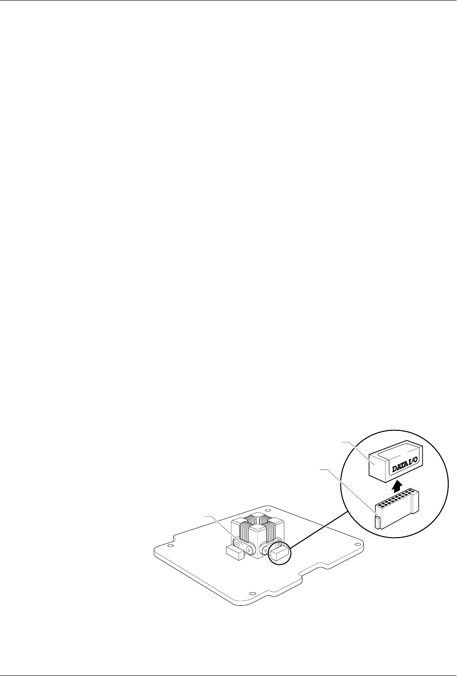
Figure 4-5
Configuring Blocks on a
Programming Module
1649-1
CONFIGURATION BLOCK
CONFIGURATION CONNECTOR
CONTACT SET
(1 of 4)
20A
1X
4X

Operation
ProMaster 2500 User Manual 4-9
Removing Modules or
Moving Configuration
Blocks
This section describes the typical steps involved in checking and
changing the configuration of your module.
1.
Select the device
—On the
Device List
disk, find the device you want
to program in the left-hand columns. The module configuration for
that device is listed in the column labeled “Base.” Sample lines from
the
Device List
disk are shown below:
Part Programmer Package Prod.
Mfr. Number Menu Name Pins Type Footnotes Base Vers.
XXX 22V10-10/-15 22V10-10-PLCC 28 PLCC 3 PLCC-28-2 1.1
XXX CE26V12H CE26V12H-PL 28 PLCC 53 PLCC-28-4 1.1
Most devices are programmed with the “-2” programming module
configuration because it supports standard power and ground pin
locations. For this sample procedure, the selected device requires
“PLCC-28-4” for the programming module configuration. This
means that the device is in a PLCC package, has 28 pins, and must be
configured as a “-4.”
Note: Modules are shipped from the factory without any configuration blocks
installed (the “-1” configuration). Check the ProMaster 2500 Device List
disk for the specific configuration required for the devices you will be
programming.
2.
Select the blocks—
In our example, we open the 28-pin
Programming Module Configuration box. This box has all the blocks
required to make any 28-pin configuration shown on the device list.
Each compartment holds one type of block, marked with a letter. See
Figure 4-6.
The drawing on the lid of the Module Configuration box shows each
28-pin PLCC configuration, the blocks required, and the positions
where they must be installed on the programming module. See
Figure 4-7. The same information is also shown on the ProMaster
Programming Module Configuration Chart on page 4-10
Figure 4-6
Configuration Box Compartments
A BCD
E
FGH
1680-1