2500_Users_Manual - 第124页
Operation 4-10 ProMa ster 25 00 U ser Ma nual Figure 4-7 sho ws that the PLCC-2 8-4 requires two conf iguration blocks ma rked “28A” i nstalled i n connectors X1 and X3 o n the programming m odule. The tw o other connect…
Operation
ProMaster 2500 User Manual 4-9
Removing Modules or
Moving Configuration
Blocks
This section describes the typical steps involved in checking and
changing the configuration of your module.
1.
Select the device
—On the
Device List
disk, find the device you want
to program in the left-hand columns. The module configuration for
that device is listed in the column labeled “Base.” Sample lines from
the
Device List
disk are shown below:
Part Programmer Package Prod.
Mfr. Number Menu Name Pins Type Footnotes Base Vers.
XXX 22V10-10/-15 22V10-10-PLCC 28 PLCC 3 PLCC-28-2 1.1
XXX CE26V12H CE26V12H-PL 28 PLCC 53 PLCC-28-4 1.1
Most devices are programmed with the “-2” programming module
configuration because it supports standard power and ground pin
locations. For this sample procedure, the selected device requires
“PLCC-28-4” for the programming module configuration. This
means that the device is in a PLCC package, has 28 pins, and must be
configured as a “-4.”
Note: Modules are shipped from the factory without any configuration blocks
installed (the “-1” configuration). Check the ProMaster 2500 Device List
disk for the specific configuration required for the devices you will be
programming.
2.
Select the blocks—
In our example, we open the 28-pin
Programming Module Configuration box. This box has all the blocks
required to make any 28-pin configuration shown on the device list.
Each compartment holds one type of block, marked with a letter. See
Figure 4-6.
The drawing on the lid of the Module Configuration box shows each
28-pin PLCC configuration, the blocks required, and the positions
where they must be installed on the programming module. See
Figure 4-7. The same information is also shown on the ProMaster
Programming Module Configuration Chart on page 4-10
Figure 4-6
Configuration Box Compartments
A BCD
E
FGH
1680-1
Operation
4-10 ProMaster 2500 User Manual
Figure 4-7 shows that the PLCC-28-4 requires two configuration
blocks marked “28A” installed in connectors
X1
and X3 on the
programming module. The two other connectors on the module (X2
and X4) are marked with an asterisk (
*)
to indicate that those
positions should be left open (empty).
3.
Remove the current blocks —
Remove the blocks currently installed
in the module and put them in the correct compartment in the box.
Blocks marked “28A” are located in compartment A.
CAUTION: Be careful when removing the configuration blocks. A
careless removal technique can result in damage to the
configuration connector or to the traces on the board.
4.
Install the new blocks—
Install the blocks in the positions shown on
the box lid’s drawing (see Figure 4-7).
5.
Install the module on the 2500
.
6.
Program devices
.
Figure 4-7
Configuration Box Lid—Optional
Configurations for 28-pin Module.
1670-1
X1
X3
X2 X4
X1
X3
X2 X4
X1
X3
X2 X4
28C
28E
28D 28B
PLCC 28-5
PLCC 28-1 PLCC 28-2 PLCC 28-3 PLCC 28-4
28A 28A
X1
X3
X2 X4
28B 28A
X1
X3
X2 X4
28A
28A
= NO CONFIGURATION BLOCK
Operation
ProMaster 2500 User Manual 4-11
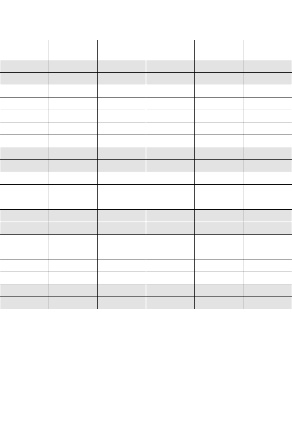
Table 4-1
ProMaster Programming Module Configuration Chart
Programming
Module Type Pin Count
Connector X1 Connector X2 Connector X3 Connector X4
PLCC-20-1 20 Open Open Open Open
PLCC-20-2 20 Open 20A Open 20A
PLCC-28-1 28 Open Open Open Open
PLCC-28-2 28 Open 28A Open 28A
PLCC-28-3 28 Open 28B Open 28A
PLCC-28-4 28 28A Open 28A Open
PLCC-28-5 28 28C 28D 28E 28B
PLCC-32-1 32 Open Open Open Open
PLCC-32-2 32 Open 32A Open 32A
PLCC-44-1 44 Open Open Open Open
PLCC-44-2 44 Open 44A Open 44A
PLCC-44-3 44 44B 44C 44B 44A
PLCC-52-1 52 Open Open Open Open
PLCC-52-2 52 52A Open 52B Open
PLCC-68-1 68 Open Open Open Open
PLCC-68-2 68 68A 68A 68A 68A
PLCC-68-3 68 68C 68B 68C 68B
PLCC-68-4 68 68D 68D 68D 68D
PLCC-84-1 84 Open Open Open Open
PLCC-84-2 84 84B 84C 84B 84A