2500_Users_Manual - 第129页
Operation ProM aster 25 00 User Manua l 4-15 The device keeper bar assembl y attaches to the mountin g block with a pin that has a detent ball on the tapered end and a handle ring on the other end (see Figure 4-12) . Thi…
Operation
4-14 ProMaster 2500 User Manual
Note: Insert square PLCC devices in the input track with pin 1 oriented toward
the back of the 2500. Insert rectangular PLCC devices (32 pin), DIP and
SOIC devices in the track with pin 1 toward the input tube.
5. Slowly turn the track adjustment knob clockwise to widen the track
until the device just drops into place on the track floor.
CAUTION: Do not close (narrow) the track width while a device is lying
flat in the track; the device leads may be damaged.
Attachment for 8-pin
150-mil SOIC Devices
The 8-pin 150-mil SOIC devices are light enough that they may not rest
flat in the input track while the input orbital assembly vibrates to advance
devices down the track. A device keeper bar assembly attached next to
the input track keeps devices in the proper position in the track. The
keeper bar is oriented parallel to and above the track, allowing 150-mil
SOIC devices to move freely down the track (see Figure 4-11).
Figure 4-10
Final Track Adjustment
1855-1
STOP GUIDE
DEVICE
OPTIC
Operation
ProMaster 2500 User Manual 4-15
The device keeper bar assembly attaches to the mounting block with a pin
that has a detent ball on the tapered end and a handle ring on the other
end (see Figure 4-12). This allows the device keeper bar assembly to be
installed easily and when processing 150 mil SOIC devices, and removed
easily when processing other devices.
Before you start a Task, install the keeper bar assembly block to the
keeper bar mounting block, which should be already be attached to the
inside of the input track with two -inch hex screws.
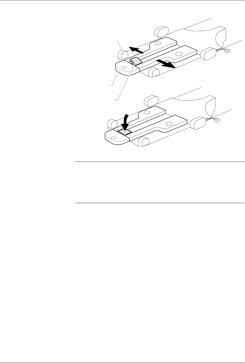
Attach the 8-pin 150-mil SOIC device keeper assembly by performing the
following procedure.
1. Insert the end of the keeper bar assembly block into the notch in the
top of the mounting block, with the keeper bar pointing to the left.
2. Insert the locking pin into the hole in the left side of the block, and
push it all the way in until you feel the detent ball click into place.
3. Swing the keeper bar toward you so that it is parallel to the input
track.
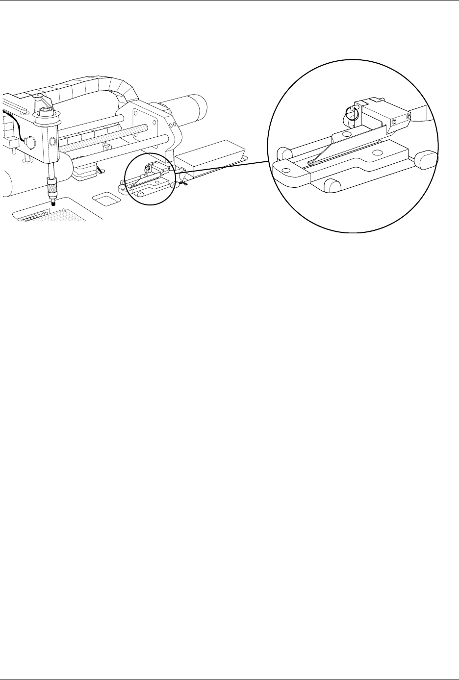
Figure 4-11
Closeup View of Input Track with 8-pin 150-mil Device Keeper Bar Assembly Installed
2500-1
332
⁄
Operation
4-16 ProMaster 2500 User Manual
Removing and
Installing Chucks
When you change to a new device package, select the appropriate chuck
as shown in the chuck selection chart (see Figure 4-13).
CAUTION: Chucks are released from the beam suddenly. If the beam is
positioned over the SPA pins or input track, the sudden
release may damage those areas.
Change the chuck with the beam directly over one of the two main plate
recesses. Keep the beam raised by holding it up with two fingers while
you use a downward pulling/twisting motion to remove the chuck. With
one hand on the beam for support, insert the new chuck by lifting it
straight up until it snaps into position.
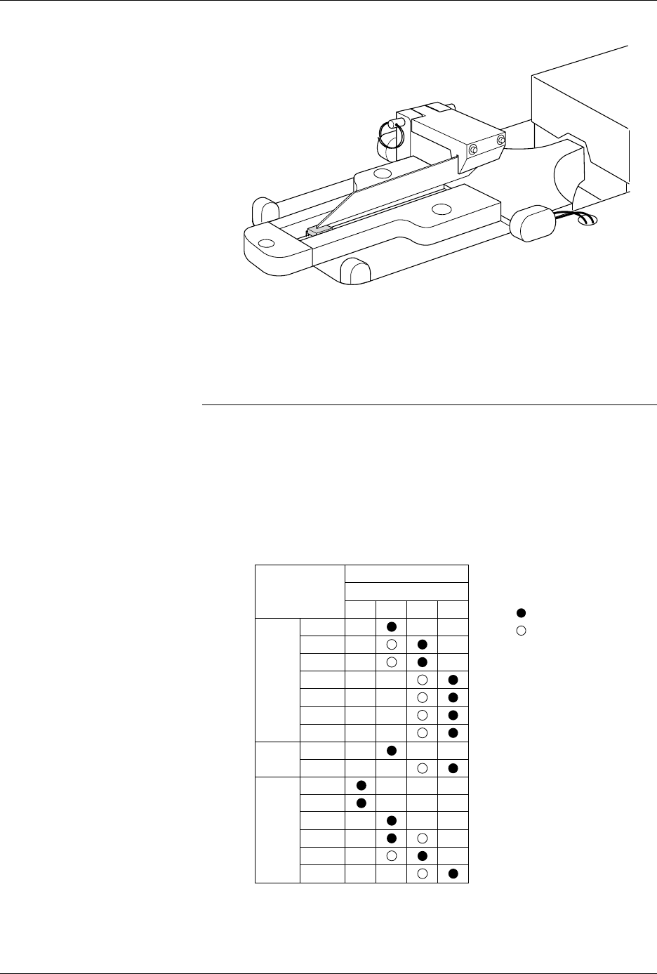
Figure 4-12
8-pin 150-mil SOIC Device Keeper
Bar Assembly Mounted in the
Input Track
Figure 4-13
Chuck Selection Chart
2501-1
DEVICE
TYPE
PLCC
DIP
LMN
20-PIN
28-PIN
32-PIN
44-PIN
52-PIN
68-PIN
84-PIN
300 mil
600 mil
1850-3
Recommended
Alternate
SOIC 150 mil
220 mil
300 mil
330 mil
420 mil
500 mil
K
CHUCK
ProMaster 2500