2500_Users_Manual - 第133页
Operation ProM aster 25 00 User Manua l 4-19 6. Unro ll ap proxima tely t wo fee t of l iner. Th read it arou nd the left of roller B , between C and D , and between the platen an d press bearings. 7. M ove roll er B to …

Operation
4-18 ProMaster 2500 User Manual
Loading Labels
The 2500 labeler prints using either a 24-wire in-line dot matrix printer or
a thermal printer. Labels usually need to be changed each time a new
device package type or different pin count is required by the Task you are
going to run. Labels are positioned on a non-adhesive liner material so
they will peel easily as they advance around the label platen’s point. The
label part number and date code are written on a label attached to the
inside of the label roll.
Note: The label part number is marked on the inner cardboard reel. You can
identify a roll of ProMaster 2500 labels by the “QF” prefix in the part
number. Labels for other Data I/O products will look the same but cannot
be used on the 2500.
The 2500 allows you to adjust where the label is applied on the device.
This parameter, called label placement, will usually be changed by the
system administrator. To place the label, the 2500’s labeler must know
where the labels are on the liner and must be able to advance the liner so
the label contacts the device at the correct time. The label detection optic
assembly (known as the ADC optic) detects the leading edge of the label
so the label drive motor can position it for correct application to the
device.
If you are switching between Kapton™ and polyester labels, check the
ADC optic value (see page 5-34) and adjust it as required so that it reads
200
when reading the label on the liner. The ADC value changes slightly
for these two label material types.
Follow the instructions in the following sections for threading the new
label stock through the appropriate printer type’s assembly.
Loading Labels in the Dot
Matrix Printer
Rollers and other components of the labeler are referred to by letters in
this section to make the threading instructions easier to follow.
Refer to Figure 4-15 andthefollowingproceduretoinstallarolloflabels.
1. Raise the application plate and slide rollers
B
and
F
in the direction
shown by the arrows in Figure 4-15. This prepares the path of the
labels to be threaded through the labeler.
2. On a standard reel, the label release knob is attached to a core pin that
holds the label roll in place. Loosen the label release knob just enough
to move it toward the center of the reel (so that the core pin no longer
protrudes), and lock the knob in this retracted position.
For a magnetic supply reel, remove the plate.
3. If labels are already installed, unthread the liner, and remove the old
label roll by putting your thumbs in the cut-outs in the supply reel
and rocking the roll back and forth as you pull it off.
4. Install the labels on the supply reel so that the label liner passes to the
left of optic
A
(see Figure 4-15).
5. If the 2500 uses a standard reel, loosen the release knob and push the
pin into the cardboard core of the label roll. Tighten the knob to hold
the pin in place against the roll’s cardboard roll.
If the 2500 uses a magnetic supply reel, reinstall the plate.
Operation
ProMaster 2500 User Manual 4-19
6. Unroll approximately two feet of liner. Thread it around the left of
roller
B
, between
C
and
D
, and between the platen and press
bearings.
7. Move roller
B
to the left so it pinches the label liner and holds it in
position. Ensure that the labels are fully aligned between the
underside of the platen and above
C
and
D
.
8. Thread the label liner across the platen and lower the application
plate to hold it in position.
9. Route the liner to the left side of roller
E
and to the right of roller
F
.
Drape the remaining liner to the left of the label advance knob.
10. Move roller
F
to the right until it snaps into position.
Note: To ensure correct label printing and application, make sure both pinch
rollers (
B
and
F
) are fully engaged.
Calibrating Labels in the
Dot Matrix Printer
The ADC (label detection) optic must be calibrated at certain times so that
labels can be correctly applied to the devices. You must calibrate this
optic whenever you:
• Change labels or the ribbon.
• Advance the labels by running the label drive motor test, turning the
label advance knob, or pulling the labels forward by hand.
• Change the ADC optic value (described on page 5-34).
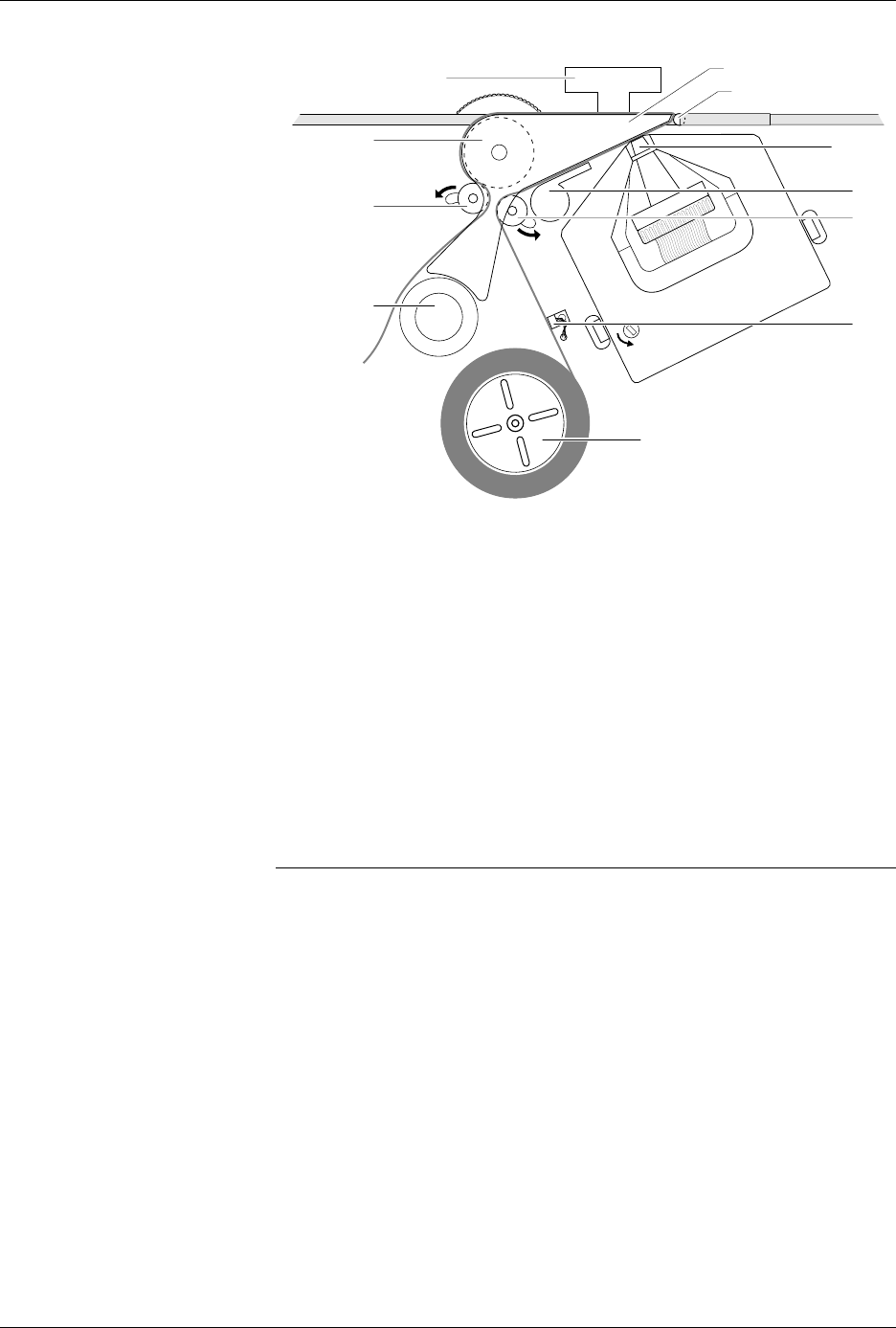
Figure 4-15
Threading New Labels in the Dot
Matrix Printer
1851-2
D
PRESS BEARINGS
PLATEN
APPLICATION PLATE
E
LABEL REEL COVER
F
B
C
A
G

Operation
4-20 ProMaster 2500 User Manual
To calibrate labels, do the following:
1. Place your finger next to the press bearings to “catch” the two or
three labels that are advanced during the calibration process.
2. Press
CAL
on the 2500’s keyboard.
3. When the labels stop advancing, calibration is complete.
Loading Labels in the
Thermal Printer
Threading labels on the thermal printer/labeler is similar to threading
labels on the dot matrix printer/labeler (see Figure 4-16). The major
differences on the thermal printer/labeler are:
• The ADC label optic is stationary.
• The retractable rollers (platen pinch and label pinch rollers) snap
back into position if you release them. On the dot matrix labeler, the
rollers remain in the open position.
Note: Do not tighten the label roll on its core. The roll is intentionally loose so
the combination of high temperature and humidity do not cause the labels
to peel incorrectly.
Follow the procedure below to load a new roll of labels into the thermal
printer.
WARNING:A hinged cover protects operators from injury while the
labeler is operating. Be sure that this cover is in place over
the labeler before you start a printing or labeling
operation.
1. Lower the labeler cover.
2. Push the label pinch roller and the platen pinch rollers into their
retracted positions away from the platen.
3. Remove the magnetic cover from the label roll.
4. Install the new label roll on the label supply hub so that the leader
comes off from the right side of the hub (see Figure 4-16).
5. Replace the magnetic cover over the label roll to hold the labels in
place.
6. Prepare the label path by raising the application plate and retracting
the platen pinch and label pinch rollers.
7. Thread about 2 feet (60 cm) of label liner around the left side of the
label alignment roller and through the gap between the application
plate and the output track. Lay the liner along the output track for the
time being.
8. Position the label liner on the underside of the platen and guide the
platen pinch roller back into its operating position against the platen
to hold the liner in place.
9. Thread the liner between the ADC optic and the platen, and then
between the print head and the platen.