2500_Users_Manual - 第139页
Operation ProM aster 25 00 User Manua l 4-25 Sumcheck Status B ox Depending o n how the ad ministrator configu red th e Task, t his box may appear if you download your device programm ing data from a fi le or load a mast…
Operation
4-24 ProMaster 2500 User Manual
Selecting a Task
To select a Task from the list presented on the screen, press
T
AB
to move
the cursor to the
Task/Kit
list box. Use the
↑
+
↓
to highlight a specific
Task name. Press
↵
to start that Task.
Selecting a Database
File
If the Task you are looking for is not displayed, it may be located in a
different Task database file. To select a different Task/Kit database file,
highlight the
Task/Kit Database
entry line and press
F2
.
Select the path and filename of the Task/Kit database file you want in the
Filename
entry field, or select it from the
Dirs/Drives
and
Files
list boxes.
Press
↵
, or select
<OK>
to accept the new database filename.
Now select the Task you want to run from the list as described above.
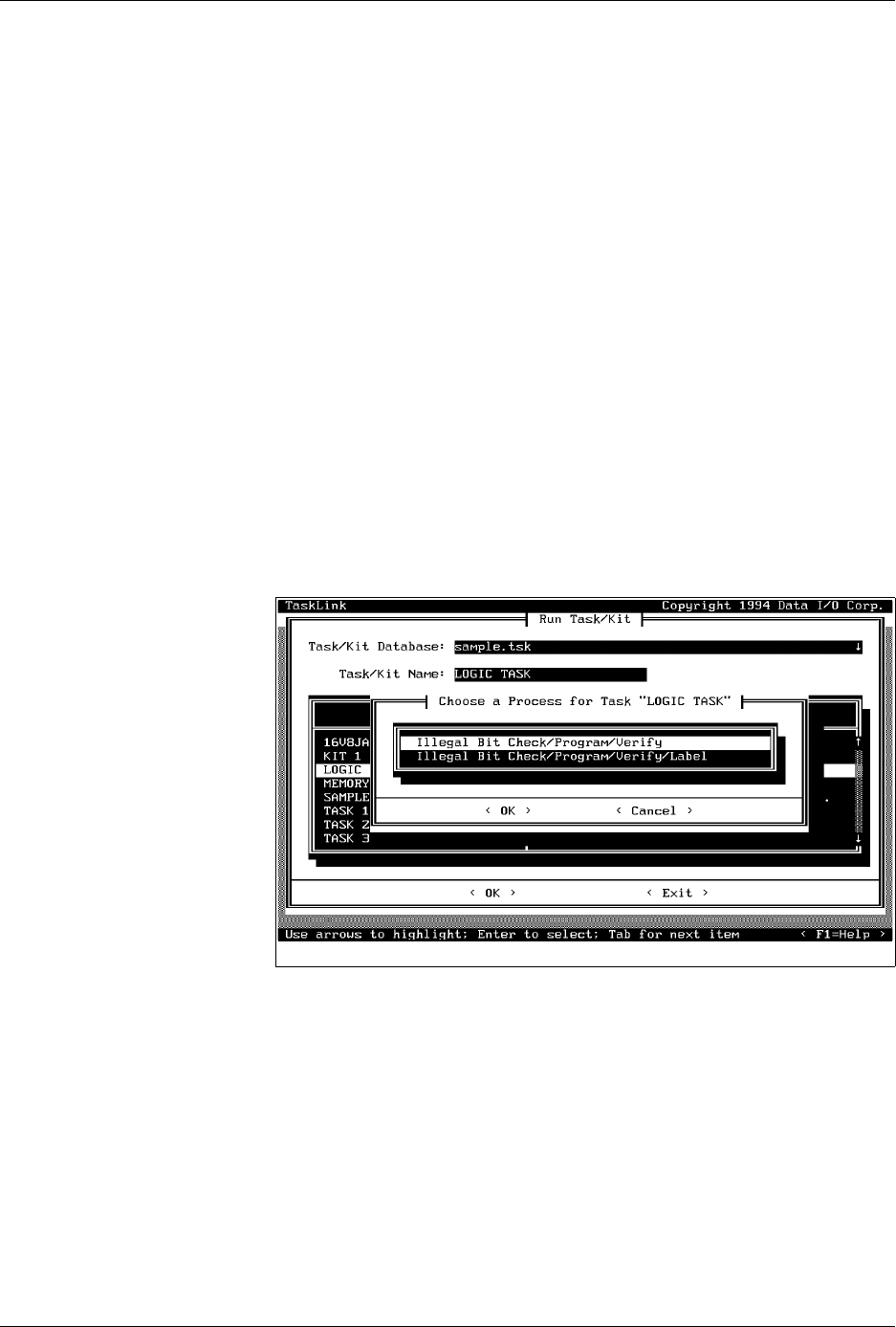
Select Process
A list of processes may appear depending on how the Task was written.
A process is a list of operations that will be performed on the devices in
the Task. If a list of processes appears, you must make a choice similar to
the one in Figure 4-19. Check the instructions you have been given to help
you decide which process to select. In this example, the only difference
between these two processes is that one does not call for labeling the
device.
Select the desired process and press
↵
.
Other Prompts
Other prompts, such as those described below, may appear depending on
the types of devices listed in the Task. Then the action status box appears
showing what percentage of the data has been loaded.
Selecting a Device
A Task-specific device list may appear asking you to select from several
device IC manufacturers. Check the tubes of devices you will be running
and select the appropriate manufacturer and device type from the screen.
Use the
↑
and
↓
keys to move the screen cursor between devices. Press
↵
to select the device and continue running the Task.
Figure 4-19
Choosing a Process From Those
Presented on the Screen
Operation
ProMaster 2500 User Manual 4-25
Sumcheck Status Box
Depending on how the administrator configured the Task, this box may
appear if you download your device programming data from a file or
load a master device. The recorded sumcheck may be displayed
(depending on how the Task was written) so you can confirm the number
with your paper documentation. Press
↵
to continue or
E
SC
to abort the
Task if there is an error.
Process Devices Dialog Box
Once TaskLink has loaded data in RAM to program the devices, the
Process Devices dialog box may appear. The
Pass Limit
field enables you
to enter the number of devices that you are going to program using this
Task. When you enter any number (other than zero), TaskLink will count
the number of devices you programmed successfully and stop when the
number you entered in the Pass Limit field has been reached.
Count the number of parts in a full tube and enter this in the
Parts/tube
field. The 2500 counts the number of devices entering the output tube and
prompts you to insert an empty tube when that number is reached.
Figure 4-20
Checking the Sumcheck
Figure 4-21
Setting Pass Limit and Parts Per
Tube

Operation
4-26 ProMaster 2500 User Manual
If you start a Task with an incorrect number in the Parts/tube field, press
STOP
and then
LOWER CASE
+
T
. Enter the correct number. Press
ENTER
and then
START
to continue running the Task.
This screen also indicates where TaskLink expects device pin 1 to be
located when the device is in the input track. This is critical for correct
device handling and insertion in the programming module socket. Make
certain that your device matches this positioning. Refer to page 4-22 for
more information on installing devices in the input tube holder.
The system automatically downloads the data file defined in your Task or
prompts you to insert a master device.
If the Task asks you to load RAM data from a master device, TaskLink
prompts you to insert the master device to be loaded. Place the device in
the input track, against the programming station stop guide. Be careful to
observe the correct orientation of pin 1.
Close the hood. The 2500 detects the device, picks it up, inserts it in the
programming module, and loads the device’s data into RAM.
After the load, the master device is set in the left device recess near the
labeler.