2500_Users_Manual - 第140页
Operation 4-26 ProMa ster 25 00 U ser Ma nual If you start a Task with an incorrect number in th e Parts/tube field, press STOP and then LOWE R CASE + T . Enter the correct number. Press ENTER and th en START to continue…
Operation
ProMaster 2500 User Manual 4-25
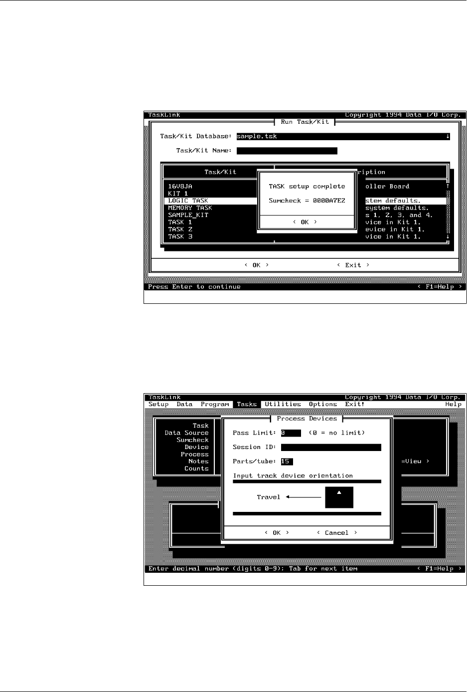
Sumcheck Status Box
Depending on how the administrator configured the Task, this box may
appear if you download your device programming data from a file or
load a master device. The recorded sumcheck may be displayed
(depending on how the Task was written) so you can confirm the number
with your paper documentation. Press
↵
to continue or
E
SC
to abort the
Task if there is an error.
Process Devices Dialog Box
Once TaskLink has loaded data in RAM to program the devices, the
Process Devices dialog box may appear. The
Pass Limit
field enables you
to enter the number of devices that you are going to program using this
Task. When you enter any number (other than zero), TaskLink will count
the number of devices you programmed successfully and stop when the
number you entered in the Pass Limit field has been reached.
Count the number of parts in a full tube and enter this in the
Parts/tube
field. The 2500 counts the number of devices entering the output tube and
prompts you to insert an empty tube when that number is reached.
Figure 4-20
Checking the Sumcheck
Figure 4-21
Setting Pass Limit and Parts Per
Tube

Operation
4-26 ProMaster 2500 User Manual
If you start a Task with an incorrect number in the Parts/tube field, press
STOP
and then
LOWER CASE
+
T
. Enter the correct number. Press
ENTER
and then
START
to continue running the Task.
This screen also indicates where TaskLink expects device pin 1 to be
located when the device is in the input track. This is critical for correct
device handling and insertion in the programming module socket. Make
certain that your device matches this positioning. Refer to page 4-22 for
more information on installing devices in the input tube holder.
The system automatically downloads the data file defined in your Task or
prompts you to insert a master device.
If the Task asks you to load RAM data from a master device, TaskLink
prompts you to insert the master device to be loaded. Place the device in
the input track, against the programming station stop guide. Be careful to
observe the correct orientation of pin 1.
Close the hood. The 2500 detects the device, picks it up, inserts it in the
programming module, and loads the device’s data into RAM.
After the load, the master device is set in the left device recess near the
labeler.

Operation
ProMaster 2500 User Manual 4-27
Aligning a Device to a PLCC Programming Module
Whenever you run a new TaskLink Task or Kit using a PLCC device, the
display on the 2500 prompts you to align the beam. Follow the procedure
below to adjust the position of the beam so that it picks the device at its
center and inserts the device into the programming module correctly.
Failure to perform the alignment and cleaning procedures may cause
premature wear of the module’s contacts and an eventual decrease in
programming yield.
Note: This alignment procedure assumes that the devices are
square PLCCs,
with pin 1 oriented toward the back of the input track
(away from
the front of the 2500). Alignment of rectangular, 32-pin PLCC devices is
described on page 4-32.
Align Beam to the Device
Follow these steps to align the beam to a device in the input track.
1. Insert a tube of devices into the input track and close the hood.
2. Start the new Task.
3. The beam positions itself over the first device and pauses. The 2500
displays:
PROGRAM/TEST ONLY
USE ARROW KEYS TO ALIGN BEAM WITH
DEVICE CENTER. PRESS [D] TO LOWER BEAM.
PRESS START TO CONTINUE.