2500_Users_Manual - 第164页
Preven tive Maint enance 5-10 ProMa ster 25 00 U ser Ma nual When the beam lowers, it is driven down by low pressure air routed through hole 12. This air enters the hi/low valve assembly through hole 19 and pus hes the b…

Preventive Maintenance
ProMaster 2500 User Manual 5-9
System Air Flow
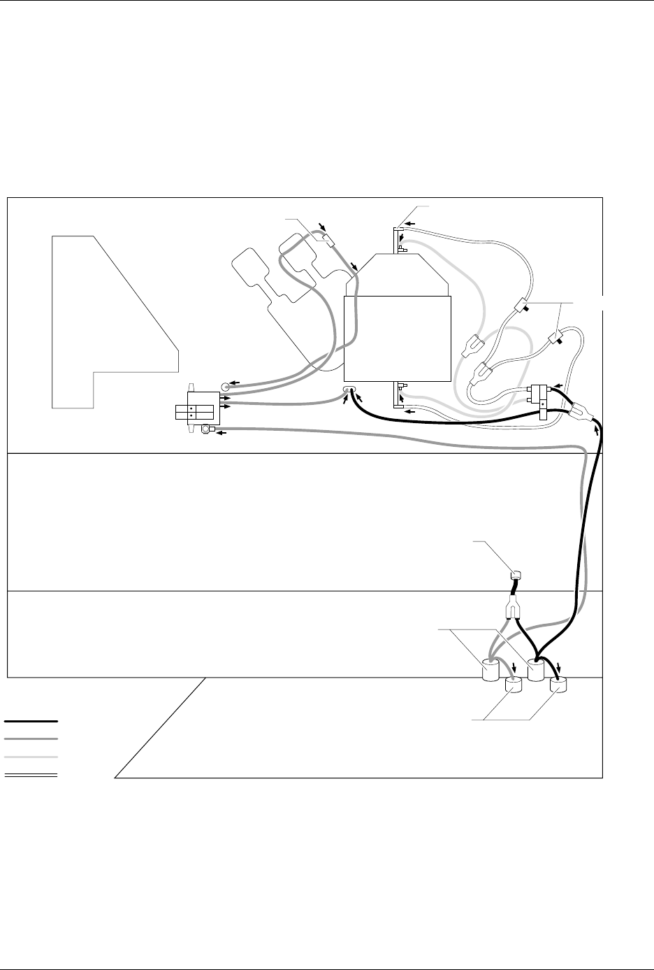
Air enters the 2500 through a 1/4-inch air connector on the rear and
branches through a Y connection to the low and high air pressure
regulators (see Figure 5-2). The air exits each regulator in two ways: to
the gauge (to display the PSI) and through the 2500 as described below.
Low air pressure should be set to 30 PSI, and high air pressure should be
set to 85 PSI. Solenoids switch high or low air pressure to the beam to
perform various functions, as shown in the table and as described in the
following sections.
Low Air Pressure
Low pressure air is routed from the low pressure regulator to a solenoid
block where it is switched to either the beam or the output track (see
Figure 5-2).
Beam Up/down
This section describes how the air pressure is routed through channels
inside the beam. Refer to Figure 5-16 for the location of the beam
solenoids and Figure 5-3 for the location of air channels as you read this
section.
After the 2500 powers up, solenoid
4
(beam up/down) forces low
pressure air through an air channel in the beam baffle plate from hole 11
to hole 10, up through the beam to hole 16 and hole 17, and finally to the
top of the fixed piston, pushing the beam assembly up into the ready
position. Low pressure air passes through the beam and a single air cap
(cavity), which dampens out air spikes and is routed directly to solenoids
4
and
5
.
High Pressure Low Pressure
Beam vacuum generators Lower beam to pick up device
Lower beam to release device
Final insertion force into
programming module
Initial insertion force into programming
module
Programming module
clamps
Device blow off
Output tube air to start device movement
Preventive Maintenance
5-10 ProMaster 2500 User Manual
When the beam lowers, it is driven down by low pressure air routed
through hole 12. This air enters the hi/low valve assembly through hole
19 and pushes the ball bearing up, sealing off hole 21 and creating a path
to hole 20. From hole 20, the low pressure air is forced to hole 18, pushing
down on the fixed piston and lowering the beam. This air is vented
through exhaust holes on the bottom of the beam assembly.
Figure 5-2
High and Low Pressure Air Lines
2054-2
MAIN PLATE (Underside)
BACK OF BASE
BOTTOM OF BASE
FRONT OF BASE
BLACK (HP)
GRAY (LP)
BLUE
RED
EXTERNAL INPUT
REGULATORS
GAUGES
REGULATORS
AIR CYLINDER (1 of 2)
BLOW REGULATOR
SOLENOID 8
TO BEAM
SOLENOIDS
2 AND 3
TO OUTPUT TUBE
PART BLOW IN
HIGH
LOW
Preventive Maintenance
ProMaster 2500 User Manual 5-11
Label Application
When solenoid
3
is selected (see Figure 5-15), low pressure air is passed to
the beam assembly. When the 2500 prepares to apply a label on a device,
the beam lowers (with low air pressure) the device on the application
plate, and then solenoid
3
is turned off to bleed the low pressure line. To
prevent the device from being skewed during label application, the beam
rests on the device (with its own weight and no air pressure) as it is
moved across the label.
Chip Blow-off
Devices are released from the chuck tip when vacuum is turned off and
low air pressure is activated to ensure a smooth separation. Beam
solenoid
5
(blow off) is activated, allowing low pressure air into the
vacuum chamber. The low pressure air does not go through the vacuum
venturi because the chamber is pressurized to 30 to 40 PSI. Instead, the air
is forced through the beam and chuck shaft, assisting the chip to separate
from the chuck tip.
Output Track Air
Low pressure air is used on the output tracks to help devices enter the
output tubes. When solenoid
2
is selected, low pressure air is switched to
both output tracks. An in-line valve, called the track air adjustment, is
located on the main plate to the right side of output tube holder 1. The air
level can be adjusted when the system is reconfigured between large and
small devices.
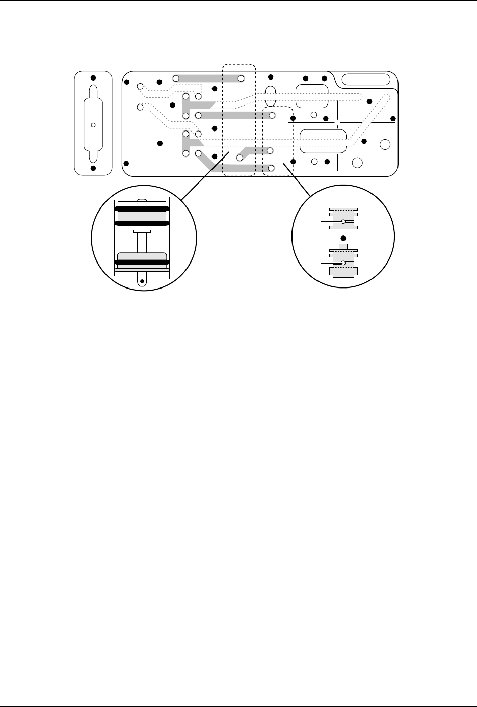
Figure 5-3
Beam Air Holes
16
17
4
5
18
20
21
19
11
12
17
18
21
20
19
2387-1
BEAM AIR
CYLINDER