2500_Users_Manual - 第169页
Preventi ve Mai nten ance ProM aster 25 00 User Manua l 5-15 Dot Matrix Label Printer The dot matrix label printer (also s imply referred to as labeler) uses a 2 x 12-w ire, in-line dot matrix print head to print labels.…
Preventive Maintenance
5-14 ProMaster 2500 User Manual
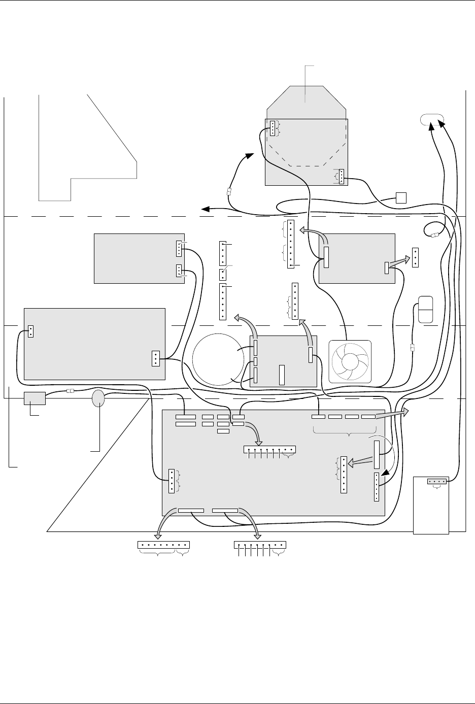
Figure 5-4
Power Supplies
MAIN PLATE (Underside)
BACK OF BASE
BOTTOM OF BASE
FRONT OF BASE
LABEL
ADVANCE
MOTOR
PRINT HEAD
P2
AC IN P1
TB2
TB1
J1
J2
J3
J4
240
220
120
100
J27
J22
J23
J24 J25
J24 J25
J3
J9 J10 J12 J13
J2
J11
*
DISK
DRIVE
AC
IN
CONTROLLER
BOARD
POWER
SUPPLY
PROGRAMMING
ELECTRONICS
POWER SUPPLY
(TO BEAM)
SOLENOID
CLAMP
(TO SOLENOIDS
2 AND 3)
CONTROLLER
BOARD
PROGRAMMING ELECTRONICS
CONTROLLER BOARD
(TO BEAM
TRAVERSE
MOTOR)
MOTORS
**
* +90V on all six pins while motor is inactive.
** Approx. 16Vac (rms) while motor is running.
FAN
TORROID
POWER
SUPPLY
LABELER
POWER SUPPLY
2055-3
1
1
120V
GND
AC IN
GND
+24V
V1
+24V
+24V GND
+24V
NC
11
1
NC
+5V
GND
+12V
NC
-12V
NC
0
24
0
24
24
24
NC
1
1
1
120Vac
120Vac
97Vac
1
+15V
NC
+90V
GND
+90V
+36V GND
+36V
GND
NC
TB2
GND
120
TB1
J1
J2
J3
J4
+90V
GND
+90V
+36V GND
+36V
J2
J10 - BEAM
ROTATE
MOTOR
J12 - INPUT
ORBITAL
MOTOR
J13 - OUTPUT
ORBITAL
MOTOR
GND
+15V
NC
GND
+15V
GND
NC
+5V

Preventive Maintenance
ProMaster 2500 User Manual 5-15
Dot Matrix Label
Printer
The dot matrix label printer (also simply referred to as labeler) uses a
2 x 12-wire, in-line dot matrix print head to print labels. The labels are on
a roll of label liner that is threaded through the labeler assembly from a
label supply reel. The labeler can print a maximum of three lines of text
on a label.
The label drive motor is the second motor mounted behind the labeler
assembly plate. It provides the drive to turn two rollers that advance the
liner through the labeler system. The black pinch roller snaps into
position to assist the label advance roller to get a firm grip on the label
liner. The timing of the label advance roller has to be precise so it can
accurately place the label on the device and ensure even spacing between
the printed characters on the label.
The 2500 lets you choose the position of the label on the device. In order
to accomplish this, the labeler must know the location of the labels on the
liner and must be able to advance the label so it contacts the device at the
correct time. On the front of the labeler assembly plate, the ADC optic
roller assembly detects the leading edge of the label. The highly sensitive
ADC optic emitter/collector pair reads the level of light that passes
through the combined label and liner during label calibration. This light
reading, called the ADC optic value, is the reference used to compare to
the higher level of light detected when only the liner passes through the
optic. This reading allows the labeler to synchronize to the leading edge
of the labels.
Character Sizes
The labeler can produce six font sizes, measured in characters per inch
(CPI). The six font sizes are listed below.
• Normal Fonts: 18, 20, and 26 CPI
• Short Font: 26 CPI
• Tall Fonts: 12, 16
Preventive Maintenance
5-16 ProMaster 2500 User Manual
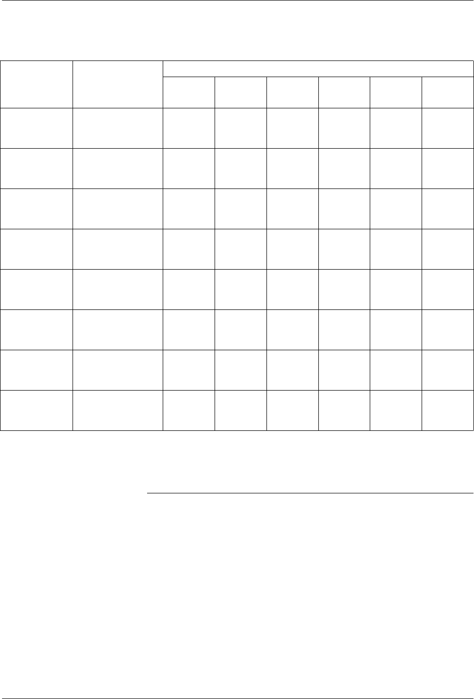
Key: CPI = Number of characters per inch
L = Number of lines that can be printed on a label
Note: By reducing the margins, you may be able to print additional characters
and lines on the labels.
Table 5-1
ProMaster 2500 Label Print Guide (Dot Matrix Printer)
Typical
Application
Label Model
Number &
Dimensions
Number of Characters per Line
12 CPI
Tall
16 CPI
Tall 18 CPI 20 CPI 26 CPI
26 CPI
*
Short
300 MIL DIP
(14-20 PIN)
QF-06-20
3/16” X 5/8”
(.187” X .625”)
7
(L=1)
10
(L=1)
11
(L=2)
11
(L=2)
15
(L=2)
15
(L=3)
300 MIL DIP
(20-28 PIN)
QF-06-24
3/16” X 3/4”
(.187” X .750”)
8
(L=1)
12
(L=1)
13
(L=2)
14
(L=2)
18
(L=2)
18
(L=3)
300 MIL DIP
(24-28 PIN)
QF-06-26
3/16” X 13/16”
(.187” X .812”)
10
(L=2)
13
(L=1)
14
(L=2)
15
(L=2)
18
(L=2)
18
(L=3)
600 MIL DIP
(24-40 PIN)
QF-14-32
7/16” X 1”
(.437” X 1.00”)
12
(L=1)
16
(L=1)
17
(L=2)
18
(L=2)
24
(L=2)
24
(L=3)
300 MIL DIP (8
PIN) or 20 PIN
PLCC
QF-06-09
3/16” X 9/32”
(.187” X .281”)
3
(L=1)
4
(L=1)
4
(L=2)
4
(L=2)
6
(L=2)
6
(L=3)
28 PIN PLCC QF-09-09
3/16” X 9/32”
(.281” X .281”)
3
(L=1)
4
(L=1)
4
(L=2)
4
(L=2)
6
(L=2)
6
(L=3)
32 PIN PLCC QF-12-12
3/8” X 3/8”
(.375” X .375”)
4
(L=1)
5
(L=1)
6
(L=2)
6
(L=2)
8
(L=2)
8
(L=3)
44 - 84 PIN
PLCC
QF-16-16
1/2” X 1/2”
(.500” X .500”)
6
(L=1)
8
(L=1)
8
(L=2)
9
(L=2)
11
(L=2)
11
(L=3)
* There will be no space between the three lines, but the characters will be readable.