2500_Users_Manual - 第171页
Preventi ve Mai nten ance ProM aster 25 00 User Manua l 5-17 Thermal Label Printer The thermal label printer (also referred to simply as the labeler) uses a thermal print head to print labels. The labels are supplied on …
Preventive Maintenance
5-16 ProMaster 2500 User Manual
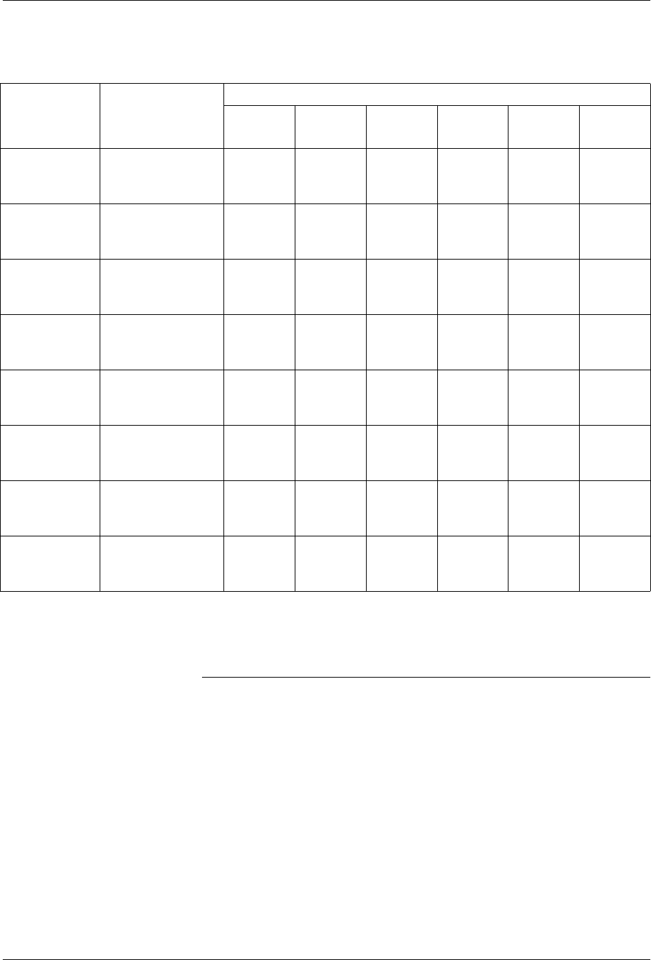
Key: CPI = Number of characters per inch
L = Number of lines that can be printed on a label
Note: By reducing the margins, you may be able to print additional characters
and lines on the labels.
Table 5-1
ProMaster 2500 Label Print Guide (Dot Matrix Printer)
Typical
Application
Label Model
Number &
Dimensions
Number of Characters per Line
12 CPI
Tall
16 CPI
Tall 18 CPI 20 CPI 26 CPI
26 CPI
*
Short
300 MIL DIP
(14-20 PIN)
QF-06-20
3/16” X 5/8”
(.187” X .625”)
7
(L=1)
10
(L=1)
11
(L=2)
11
(L=2)
15
(L=2)
15
(L=3)
300 MIL DIP
(20-28 PIN)
QF-06-24
3/16” X 3/4”
(.187” X .750”)
8
(L=1)
12
(L=1)
13
(L=2)
14
(L=2)
18
(L=2)
18
(L=3)
300 MIL DIP
(24-28 PIN)
QF-06-26
3/16” X 13/16”
(.187” X .812”)
10
(L=2)
13
(L=1)
14
(L=2)
15
(L=2)
18
(L=2)
18
(L=3)
600 MIL DIP
(24-40 PIN)
QF-14-32
7/16” X 1”
(.437” X 1.00”)
12
(L=1)
16
(L=1)
17
(L=2)
18
(L=2)
24
(L=2)
24
(L=3)
300 MIL DIP (8
PIN) or 20 PIN
PLCC
QF-06-09
3/16” X 9/32”
(.187” X .281”)
3
(L=1)
4
(L=1)
4
(L=2)
4
(L=2)
6
(L=2)
6
(L=3)
28 PIN PLCC QF-09-09
3/16” X 9/32”
(.281” X .281”)
3
(L=1)
4
(L=1)
4
(L=2)
4
(L=2)
6
(L=2)
6
(L=3)
32 PIN PLCC QF-12-12
3/8” X 3/8”
(.375” X .375”)
4
(L=1)
5
(L=1)
6
(L=2)
6
(L=2)
8
(L=2)
8
(L=3)
44 - 84 PIN
PLCC
QF-16-16
1/2” X 1/2”
(.500” X .500”)
6
(L=1)
8
(L=1)
8
(L=2)
9
(L=2)
11
(L=2)
11
(L=3)
* There will be no space between the three lines, but the characters will be readable.

Preventive Maintenance
ProMaster 2500 User Manual 5-17
Thermal Label
Printer
The thermal label printer (also referred to simply as the labeler) uses a
thermal print head to print labels. The labels are supplied on a roll of
label liner that is threaded through the labeler assembly from a label
supply reel. The number of lines that the labeler can print on a label is
determined by the size of the font selected.
The label drive motor is the only motor mounted behind the labeler
assembly plate. It provides the drive to turn two rollers that advance the
liner through the labeler system as well as two rollers that advance the
ribbon through the labeler system. The black pinch roller snaps into
position to assist the label drive roller to get a firm grip on the label liner.
The timing of the label advance roller has to be precise so it can
accurately place the label on the device and ensure even spacing between
the printed characters on the label.
The 2500 lets you choose the position of the label on the device. In order
to accomplish this, the labeler must know the location of the labels on the
liner and must be able to advance the label so it contacts the device at the
correct time. On the front of the labeler assembly plate, the ADC optic
detects the leading edge of the label. The highly sensitive ADC optic
emitter/collector pair reads the level of light that passes through the
combined label and liner during label calibration. This light reading,
called the ADC optic value, is the reference level used to detect the
increased level of light passing through the liner alone. This reading
allows the labeler to synchronize with the leading edge of the labels.
Character Sizes
The labeler can produce six font sizes, measured in characters per inch
(CPI). The six font sizes are listed below (firmware version 1.24 or higher).
• Normal Fonts: 11, 16, 19, 22, and 28 CPI
• Short Font: 28 CPI
Preventive Maintenance
5-18 ProMaster 2500 User Manual
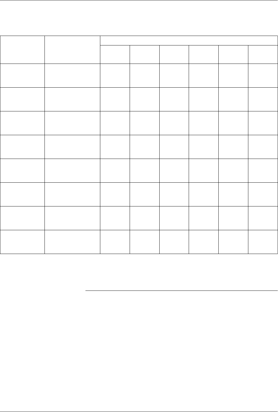
Key: CPI = Number of characters per inch
L = Number of lines that can be printed on a label
Note: By reducing the margins, you may be able to print additional characters
and lines on the labels.
Table 5-2
ProMaster 2500 Label Print Guide (Thermal Printer)
Typical
Application
Label Model
Number &
Dimensions
Number of Characters per Line
11 CPI 16 CPI 19 CPI 22 CPI 28 CPI
28 CPI
*
Short
300 MIL DIP
(14-20 PIN)
QF-06-20
3/16” X 5/8”
(.187” X .625”)
6
(L=1)
10
(L=1 )
11
(L=2)
13
(L=2)
17
(L=2)
17
(L=3)
300 MIL DIP
(20-28 PIN)
QF-06-24
3/16” X 3/4”
(.187” X .750”)
8
(L=1)
12
(L=1)
14
(L=2)
16
(L=2)
20
(L=2)
21
(L=3)
300 MIL DIP
(24-28 PIN)
QF-06-26
3/16” X 13/16”
(.187” X .812”)
8
(L=2)
13
(L=1)
15
(L=2)
17
(L=2)
22
(L=2)
22
(L=3)
600 MIL DIP
(24-40 PIN)
QF-14-32
7/16” X 1”
(.437” X 1.00”)
11
(L=1)
16
(L=1)
18
(L=2)
21
(L=2)
26
(L=2)
26
(L=3)
300 MIL DIP
(8 PIN) or
20 PIN PLCC
QF-06-09
3/16” X 9/32”
(.187” X .281”)
3
(L=1)
4
(L=1)
5
(L=2)
6
(L=2)
7
(L=2)
7
(L=3)
28 PIN PLCC QF-09-09
3/16” X 9/32”
(.281" X .281")
3
(L=1)
4
(L=1)
5
(L=2)
6
(L=2)
7
(L=2)
7
(L=3)
32 PIN PLCC QF-12-12
3/8” X 3/8”
(.375” X .375”)
4
(L=1)
5
(L=1)
7
(L=2)
8
(L=2)
10
(L=2)
10
(L=3)
44 - 84 PIN
PLCC
QF-16-16
1/2” X 1/2”
(.500” X .500”)
5
(L=1)
8
(L=1)
9
(L=2)
10
(L=2)
13
(L=2)
13
(L=3)
* There will be no space between the three lines, but the characters will be readable.