2500_Users_Manual - 第183页
Preventi ve Mai nten ance ProM aster 25 00 User Manua l 5-29 Figure 5-9 Thermal Printer Ribbon Path 2304-2 PRINT HEAD (Retracted position) RIBBON ALIGNMENT ROLLER 2 RIBBON ALIGNMENT ROLLER 1 RIBBON DETECT OPTIC RIBBON RO…

Preventive Maintenance
5-28 ProMaster 2500 User Manual
5. If necessary, remove the two screws that hold the guard in place.
Loosen the collar and remove the ribbon drive roller assembly from
the printer. Hold the roller with one hand and turn it with the other.
If more than a small amount of friction is felt, adjust the collar
counterclockwise until only a slight amount of friction is felt.
Note: If the ribbon drive roller assembly has a Belleville washer rather than a
finger spring washer (Part Number 265-4485-901), it should be replaced
with the finger spring washer, fingers out, followed by the washer, and
finally the collar, which allows for a greater range of adjustment.
6. Install the adjusted ribbon drive roller assembly by sliding the
complete assembly onto the shaft. Hold the assembly in place with
your index finger on the center of the drive pulley and thumb on the
ribbon drive roller, and tighten the collar with the assembly held in.
You might have to hold the back side of the clutch so the shaft does
not slide back.
Note: The collar tightens most easily and securely when the slots on the collar
are aligned with the slots on the ribbon drive roller.
7. Install the guard and check to make sure the ribbon drive roller is not
dragging against the guard. If the roller contacts the guard, shim the
guard out slightly using one or more flat washers.
8. Check the take-up roller. It should have only slight friction. Then
adjust the clutch on the shaft on the inside of the printer, if needed.
9. To check the adjustment, run PRINT ONLY mode and make sure all
of the following are true:
• Print quality is good (crisp, clear, legible, and properly aligned).
• Ribbon does not get caught in the application area.
• Ribbon takes up properly.
• Ribbon does not move during calibration.
Preventive Maintenance
ProMaster 2500 User Manual 5-29
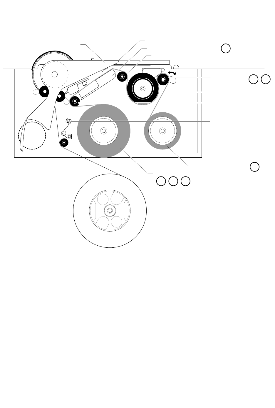
Figure 5-9
Thermal Printer Ribbon Path
2304-2
PRINT HEAD (Retracted position)
RIBBON ALIGNMENT ROLLER 2
RIBBON ALIGNMENT
ROLLER 1
RIBBON DETECT OPTIC
RIBBON ROLL
RIBBON PINCH
ROLLER
RIBBON DRIVE ROLLER
PLATEN
RIBBON TAKE-UP ROLL
APPLICATION AREA
123
4
56
8
Preventive Maintenance
5-30 ProMaster 2500 User Manual
Diagnostics
The Diagnostics option allows you to run the diagnostic tests. Refer to
Figure 5-10 for the Diagnostic command tree and refer to Appendix C for
the 2500 wiring diagram and a diagram of the handler controller board
layout.
Put the 2500 in local mode to access the Diagnostics menu. Press
4
from
the Main Menu. The following Diagnostic menu appears:
Running Diagnostic
Tests with the Hood
Up
A safety interlock switch is located behind the hood to detect when the
hood is raised. To eliminate the risk of possible injury to the operator, the
2500 will not run any motor operations that move the beams, shuttles, or
the laser shutter while the hood is raised. Some of the solenoid and motor
tests require close observation of handler components located under the
hood while they are moving to perform specific operations. While these
diagnostic tests are run, the hood must be raised so service personnel can
position themselves to observe and evaluate the operation.
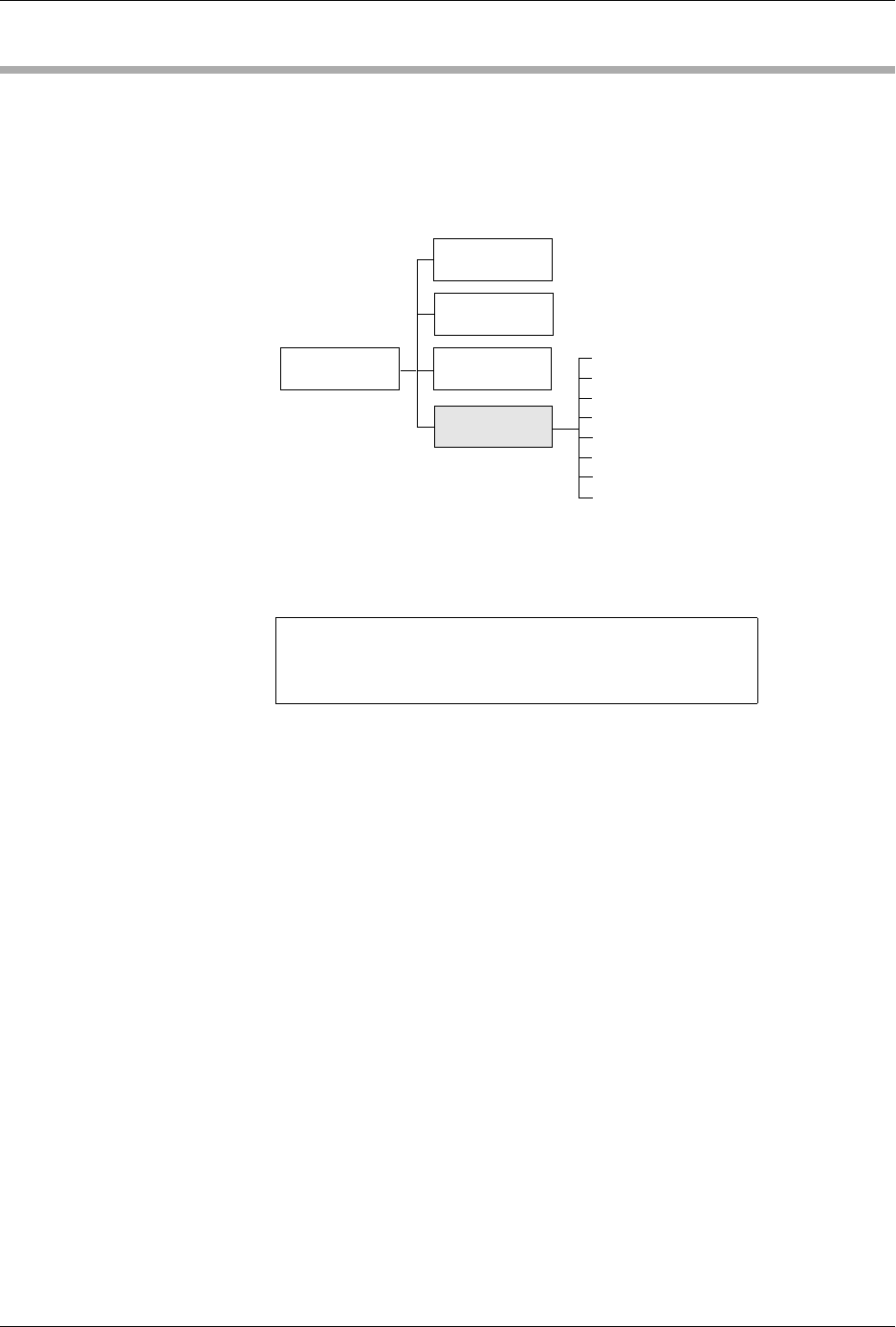
Figure 5-10
Diagnostics Command Tree
1 - OPTIC TEST 5 - PRINT TEST
2 - SOLENOID TEST 6 - KEY/DISP. TEST
3 - MOTOR TEST 7 - EEPROM TEST
4 - CYCLE PARTS 8 - COMMUNICATIONS
SYSTEM
SETUP
MAIN MENU
FILE
UTILITIES
OPERATIONS
1320-2
Optic Test
Solenoid Test
Motor Test
Cycle Parts
Print Test
Key/Display Test
EEPROM Test
Communications
DIAGNOSTICS