2500_Users_Manual - 第185页
Preventi ve Mai nten ance ProM aster 25 00 User Manua l 5-31 Hood In terloc k Key A hood interlock key is provided with each ha ndler to allow service person nel to sim ulate a closed hood in order to run di agnos tic te…
Preventive Maintenance
5-30 ProMaster 2500 User Manual
Diagnostics
The Diagnostics option allows you to run the diagnostic tests. Refer to
Figure 5-10 for the Diagnostic command tree and refer to Appendix C for
the 2500 wiring diagram and a diagram of the handler controller board
layout.
Put the 2500 in local mode to access the Diagnostics menu. Press
4
from
the Main Menu. The following Diagnostic menu appears:
Running Diagnostic
Tests with the Hood
Up
A safety interlock switch is located behind the hood to detect when the
hood is raised. To eliminate the risk of possible injury to the operator, the
2500 will not run any motor operations that move the beams, shuttles, or
the laser shutter while the hood is raised. Some of the solenoid and motor
tests require close observation of handler components located under the
hood while they are moving to perform specific operations. While these
diagnostic tests are run, the hood must be raised so service personnel can
position themselves to observe and evaluate the operation.
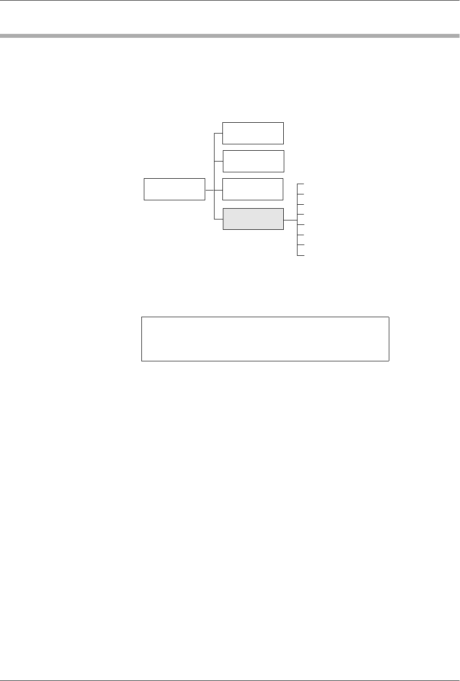
Figure 5-10
Diagnostics Command Tree
1 - OPTIC TEST 5 - PRINT TEST
2 - SOLENOID TEST 6 - KEY/DISP. TEST
3 - MOTOR TEST 7 - EEPROM TEST
4 - CYCLE PARTS 8 - COMMUNICATIONS
SYSTEM
SETUP
MAIN MENU
FILE
UTILITIES
OPERATIONS
1320-2
Optic Test
Solenoid Test
Motor Test
Cycle Parts
Print Test
Key/Display Test
EEPROM Test
Communications
DIAGNOSTICS
Preventive Maintenance
ProMaster 2500 User Manual 5-31
Hood Interlock Key
A hood interlock key is provided with each handler to allow service
personnel to simulate a closed hood in order to run diagnostic tests.
When the key is in position, the 2500 detects a lowered hood and will
perform the solenoid and motor tests while the hood is raised. The hood
cannot be lowered fully into its operating position while the key is
installed.
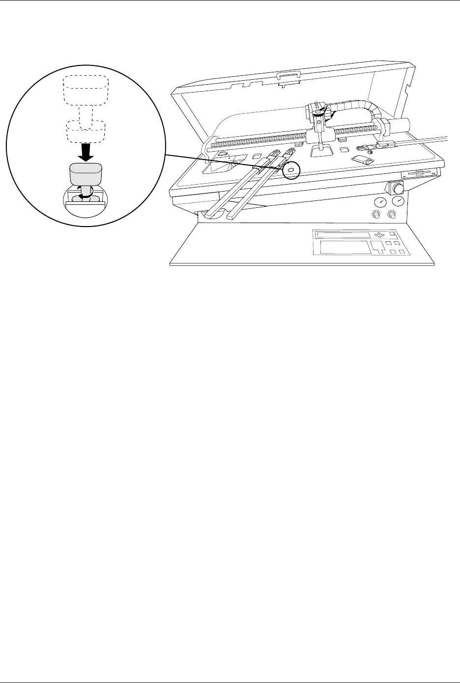
Perform the following steps to install the key (see Figure 5-11).
1. Raise the hood while the 2500 is idle.
2. Insert the key into the hood interlock key hole.
3. Turn the key 1/4-turn clockwise to lock the key in position.
4. Select and run the desired diagnostic test.
Figure 5-11
Inserting the Hood Interlock Switch
2516-1

Preventive Maintenance
5-32 ProMaster 2500 User Manual
Optic Test
The optic test verifies that the optics and microswitches are working
correctly. To access the optic test, press
1
from the Diagnostics menu. The
2500 displays:
where ADC represents the value when the label or liner is present, VAC
represents the amount of beam vacuum, ENC is the traverse beam motor
encoder position, U15 REV X.XX and U43 REV X.XX represents the
version numbers of the 2500 firmware.
The numbers on the second line of the display represent optic or
switches, either blocked (0) or unblocked (1). Optic and switch
identification is shown in the table below; their locations are shown in
Figure 5-12.
To test the optics, follow the procedure below for each test.
1. Block the optic in the track with an opaque object.
2. Insert a tube in each input and output bin.
3. Slowly move the beam to the limit of its travel.
4. Gently push down on the beam head.
As the optic changes from unblocked (1) to blocked (0), you should hear a
beep tone as the corresponding optic value on the display changes from
(1) to (0). If an optic is not functioning properly, no tone is audible and
the display does not change.
CAUTION: Some optics are very close to each other. Therefore, to avoid
incorrect results, make sure the opaque object blocks only the
optic you want to test.
OPTIC TEST - ADC = 200 - VAC = XX
11100000001111101111111100 ENC = 13107
| | | | | U15 REV X.XX
5 10 15 20 25 U43 REV X.XX
Test Function Test Function
1 Device out of input tube 16 Output track motor CAL
2 Device detect 17 Beam reference position
3 Beam down 18 Out of labels detect
4 Beam up 19 Input tube detect
5 Unused 20 Output tube 1 detect
6 Unused 21 Output tube 2 detect
7 Unused 22 Front prog. module clamp
8 Unused 23 Rear prog. module clamp
9Unused 24Hood up
10 Unused 25 Main plate up
11 Device release, track 1 (Dot matrix printer)/
12 Device at output tube 1 End of ribbon (Thermal printer)
13 Device release, track 2 26 Unused (Dot matrix printer)/
14 Device at output tube 2 Ribbon pinch roller open
15 Input track motor CAL (Thermal printer)