2500_Users_Manual - 第187页
Preventi ve Mai nten ance ProM aster 25 00 User Manua l 5-33 • Tests 1 and 2, and 11 throug h 14 — Trigger these optics by blo cking them wi th an opaque o bject. • Tests 3 and 4 — Push straight down on the beam head to …

Preventive Maintenance
5-32 ProMaster 2500 User Manual
Optic Test
The optic test verifies that the optics and microswitches are working
correctly. To access the optic test, press
1
from the Diagnostics menu. The
2500 displays:
where ADC represents the value when the label or liner is present, VAC
represents the amount of beam vacuum, ENC is the traverse beam motor
encoder position, U15 REV X.XX and U43 REV X.XX represents the
version numbers of the 2500 firmware.
The numbers on the second line of the display represent optic or
switches, either blocked (0) or unblocked (1). Optic and switch
identification is shown in the table below; their locations are shown in
Figure 5-12.
To test the optics, follow the procedure below for each test.
1. Block the optic in the track with an opaque object.
2. Insert a tube in each input and output bin.
3. Slowly move the beam to the limit of its travel.
4. Gently push down on the beam head.
As the optic changes from unblocked (1) to blocked (0), you should hear a
beep tone as the corresponding optic value on the display changes from
(1) to (0). If an optic is not functioning properly, no tone is audible and
the display does not change.
CAUTION: Some optics are very close to each other. Therefore, to avoid
incorrect results, make sure the opaque object blocks only the
optic you want to test.
OPTIC TEST - ADC = 200 - VAC = XX
11100000001111101111111100 ENC = 13107
| | | | | U15 REV X.XX
5 10 15 20 25 U43 REV X.XX
Test Function Test Function
1 Device out of input tube 16 Output track motor CAL
2 Device detect 17 Beam reference position
3 Beam down 18 Out of labels detect
4 Beam up 19 Input tube detect
5 Unused 20 Output tube 1 detect
6 Unused 21 Output tube 2 detect
7 Unused 22 Front prog. module clamp
8 Unused 23 Rear prog. module clamp
9Unused 24Hood up
10 Unused 25 Main plate up
11 Device release, track 1 (Dot matrix printer)/
12 Device at output tube 1 End of ribbon (Thermal printer)
13 Device release, track 2 26 Unused (Dot matrix printer)/
14 Device at output tube 2 Ribbon pinch roller open
15 Input track motor CAL (Thermal printer)
Preventive Maintenance
ProMaster 2500 User Manual 5-33
•
Tests 1 and 2, and 11 through 14
—Trigger these optics by blocking
them with an opaque object.
•
Tests 3 and 4
—Push straight down on the beam head to perform
these two tests.
•
Tests 15 and 16
—Lift the main plate and slowly turn the input and
output orbital motors in one direction to trigger these optics.
•
Test 17
—Push the beam slowly to your right. As it gets close to the
end of its travel, the optic is triggered.
•
Test 18
—Remove the label liner from in front of this optic.
•
Tests 19 through 21
—These optics check the operation of the
microswitches on the three tube holders. Insert a tube in each to test
the switches.
•
Tests 22 and 23
—Press
C
to toggle the programming module clamps.
•
Test 24
—Lift the hood.
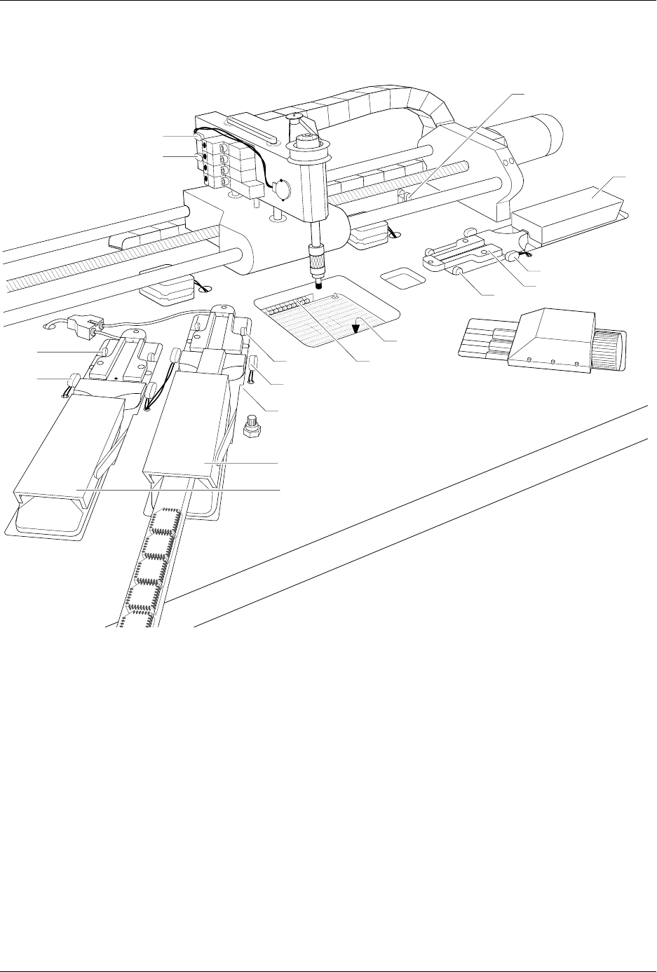
Figure 5-12
Optic and Microswitch Locations
1939-1
1
15 (Under main plate)
2
17
3
4
13
14
20 (Output tube 1)
21 (Output tube 2)
19
11
12
16 (Under main plate)
22
23

Preventive Maintenance
5-34 ProMaster 2500 User Manual
•
Test 25
—Lift the main plate.
•
VAC
—Press
V
to toggle the vacuum generator on and off. When the
vacuum generator is on, place your finger over the end of the chuck
to seal the opening and the VAC value should be greater than or
equal to 140.
Adjusting the ADC (Label
Detecting) Optic on the Dot
Matrix Printer
You may need to adjust the ADC optic if you have trouble with label
calibration, label position, or location of printed text, especially if you
have just changed labels.
To adjust the ADC value, select OPTIC TEST from the DIAGNOSTIC
MENU and load labels. Locate the ADC optic (see Figure 5-13) and
ensure that a label is blocking the optic’s beam to ensure the maximum
ADC optic value.
The 2500 should display:
If a label is not blocking the ADC optic, slowly turn the label advance
knob counterclockwise to advance the liner. The value on the display
fluctuates until the label blocks the optic and the highest value appears.
Do not begin the adjustment procedure until you are certain that a label is
blocking the optic.
If the ADC value does not reach 200, from the Optics diagnostics menu
press
LOWER CASE
+
A
, and then press
↑
or
↓
until the displayed value
reaches 200.
Turn the label advance knob until the ADC optic reads only the liner.
This should read between 120 to 170 if the liner is translucent. The liner
reading is variable, so there is no adjustment for it.
Return to the Main Menu by pressing
RESET
. Press
CAL
to have the 2500
run a label calibration to adjust to the new setting.
OPTIC TEST - ADC = 200 - VAC = 23
11100000001111101111111100 ENC = 13107
| | | | | U15 REV 1.00
5 10 15 20 25 U43 REV 1.00