2500_Users_Manual - 第214页
Preven tive Maint enance 5-60 ProMa ster 25 00 U ser Ma nual 5. Gu ide the pinch roll er back into its opera ting positio n against the drive roller. 6. Use the tape supplied on the end of the leade r (or a DIP label) to…
Preventive Maintenance
ProMaster 2500 User Manual 5-59
Replacing a Thermal
Printer Ribbon
When the ribbon roll runs out install a new roll to replace it. Each new
ribbon roll has a long leader to thread through the labeler. Follow the
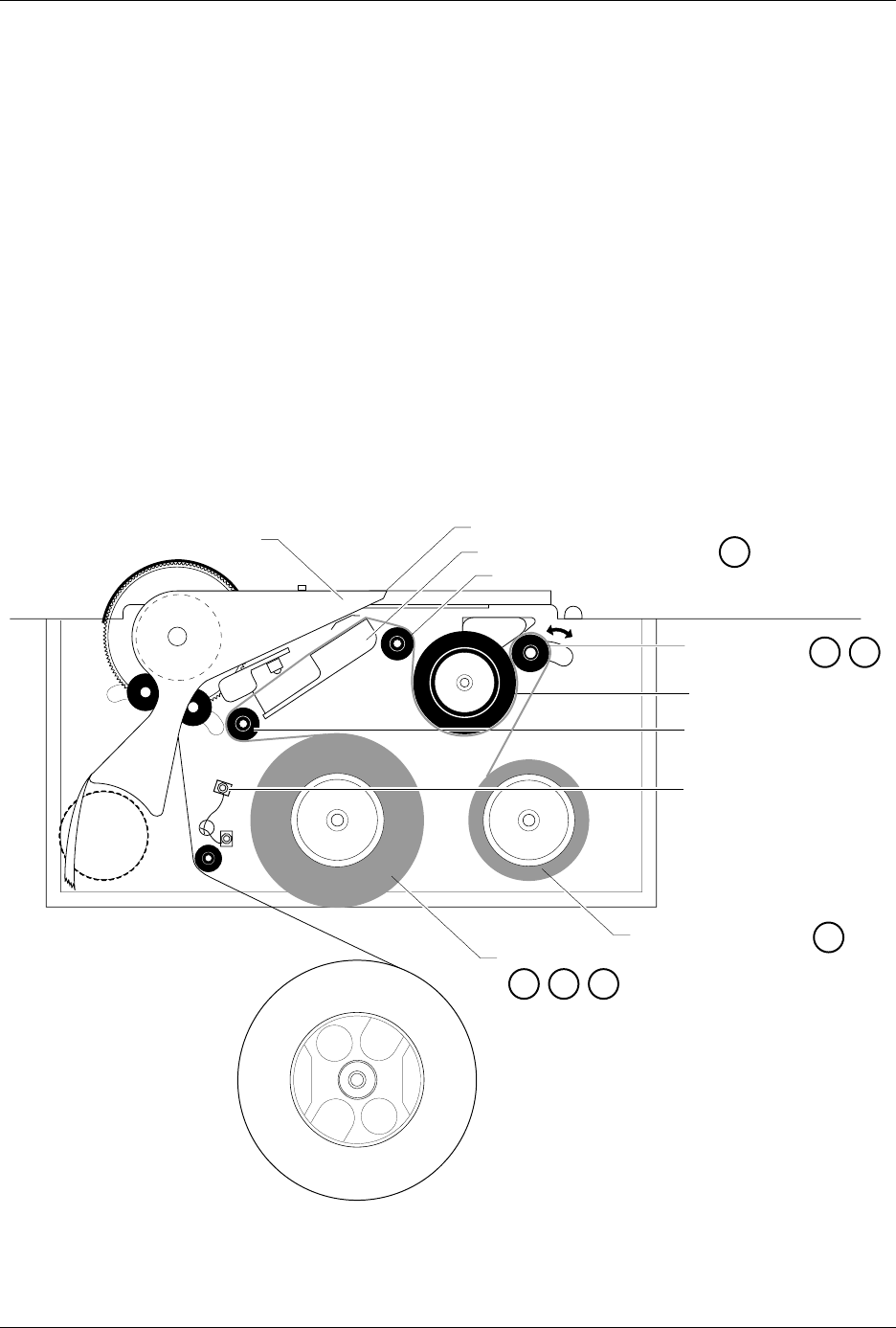
procedure below to install the new ribbon (refer to Figure 5-25).
1. Prepare the ribbon threading path by pushing the ribbon pinch roller
to the right.
2. Install the ribbon take-up core (one empty core is supplied with the
printer) on the ribbon take-up hub. After threading the ribbon, you
will tape the ribbon’s leader to this cardboard core.
3. Thread the ribbon leader over the ribbon alignment roller 1, over the
print head, and over ribbon alignment roller 2.
4. Thread the ribbon leader under the ribbon drive roller, over the
ribbon pinch roller, and down to the ribbon take-up roll (see Figure
5-25).
Figure 5-25
Threading the Ribbon in the Thermal Printer
2304-2
PRINT HEAD (Retracted position)
RIBBON ALIGNMENT ROLLER 2
RIBBON ALIGNMENT
ROLLER 1
RIBBON DETECT OPTIC
RIBBON ROLL
RIBBON PINCH
ROLLER
RIBBON DRIVE ROLLER
PLATEN
RIBBON TAKE-UP ROLL
APPLICATION AREA
123
4
56
8

Preventive Maintenance
5-60 ProMaster 2500 User Manual
5. Guide the pinch roller back into its operating position against the
drive roller.
6. Use the tape supplied on the end of the leader (or a DIP label) to
attach the leader to the take-up cardboard core.
7. When you install a new ribbon, remove the old ribbon’s cardboard
core and install it on the take-up hub as the new ribbon take-up core.
8. Turn the ribbon take-up roll counterclockwise to advance the ribbon
until it (not the leader) is between the print head and the platen.
Repairing a Torn
Thermal Printer
Ribbon
Under normal circumstances you should not have a problem with the
ribbon tearing. If it does tear, follow the procedure below to repair it.
1. Cut the end of the ribbon to remove the tear and create a straight end.
2. Cut about 16 inches (40 cm) of old label liner (hanging from the label
drive roller) to use as ribbon leader.
3. Line up the end of the ribbon with the end of the liner and tape the
two ends together (a DIP label can also be used as a tape splice).
4. Turn the splice over and tape the other side.
5. Wrap the liner around the ribbon roll once, and then follow the
instructions for installing a new ribbon. If the ribbon begins to slide
off the roll while you are threading, place a large label across the edge
of the ribbon roll to stop the unraveling. Remove this label when you
have finished threading and before you start processing devices.
Preventive Maintenance Procedures For Service Technicians
This section of the manual provides the ProMaster 2500 service technician
with a guideline for component cleaning or replacement.
To clean the 2500, you will need the following items:
• Lint-free cloth
• TriFlow® lubricant
•DeoxIT
™
Pen
• Solvent that has been approved for use by your company
• All-purpose spray cleaner
•Isopropyl alcohol
•Cotton swabs
• Compressed air
• Needle-nose pliers
• Hex drivers for hex socket head screws

Preventive Maintenance
ProMaster 2500 User Manual 5-61
Cleaning Guidelines
Cleaning the Beam
Follow the steps below to clean and lubricate the beam.
CAUTION: This procedure should be performed only by a qualified
service technician or by the system administrator.
1. Turn off the 2500 and remove the power cord.
2. With a clean, dry cloth, wipe the center connecting rod and the two
outer beam guide posts until no lubricant or dirt remains.
3. With the beam raised, place a drop of TriFlow lubricant on the lower
part of each of the two outer beam guide posts.
4. With the beam lowered, place a drop of TriFlow lubricant on the
upper part of each of the two outer beam guide posts.
5. Move the beam down and up, in a plunging motion, so the lubricant
spreads evenly along the outer beam guide posts.
6. With a clean cloth, wipe excess lubricant from the outer beam guide
posts.
Replacing the Beam Filter
Follow the steps below to replace the beam filter.
CAUTION: This procedure should be performed only by a qualified
service technician or by the system administrator.
1. Turn off the 2500 and remove the power cord.
2. Remove the two thumb-screws on either side of the clear-plastic
beam filter cover plate.
3. Remove the beam filter cover plate.
4. Use needle-nose pliers to remove the beam filter. Examine the beam
filter and replace it if it is dirty or wet.
Cleaning Programming
Module Contacts
It is extremely important to keep the programming modules clean to
extend the life of the contacts. To clean the modules at the appropriate
intervals, as described below, you must
keep an ongoing record
of the
number of device insertions for each programming module. One method
of logging the number of devices that have been programmed is to use
TaskLink’s Session Data Logging feature. This option logs all TaskLink
operations and records the results in a file on your PC, thereby tracking the
number of devices programmed on the 2500.
Follow the procedure below to thoroughly clean the programming
module contacts after every 10,000 devices (which is weekly if you
process 40,000 devices per month on the module). Perform the procedure
more often if you experience continuity-related programming problems.
If you notice debris in the programming module at any time while
running devices in a job, press
STOP
and clean the module with
compressed air. You can then press
START
to continue running the job.