2500_Users_Manual - 第217页
Preventi ve Mai nten ance ProM aster 25 00 User Manua l 5-63 Cleaning and Lubr icating the Beam L ead Screw Lubricate the lead screw, beam shaft, and carri age shafts (see Figu re 5-26) approximately every three months o…

Preventive Maintenance
5-62 ProMaster 2500 User Manual
Follow the steps below to clean the PLCC module’s contacts.
CAUTION: This procedure should be performed only by a qualified
service technician or by the system administrator.
1. Blow compressed air into the top of the programming module to
remove any device package debris. Use a rotating motion with the air
nozzle to ensure that you reach all areas.
2. Use the DeoxIT pen to apply conditioner directly to the module’s
contacts. From the base of each contact, draw the pen’s tip up the
length of each contact.
3. Crumple a small amount of soft lint-free cloth, and push it into the
programming module.
4. Install a chuck in the beam, and move it over the programming
station.
5. Set a device, oriented correctly, on the programming module.
6. Move the beam down and up (in a plunging motion) so the device
presses the cloth in the programming module along the full length of
the contacts. Pull on the cloth to lift the device out of the module.
Repeat this process several times.
7. Carefully remove the cloth.
8. With a new cloth, clean the inside of the module (as described in
steps 2 through 5). Repeat the process until the cloth comes out clean
and all the residue is gone.
9. Blow compressed air into the programming module again to remove
any conditioner that has accumulated at low points.
Note: To prevent the first few devices from sticking to the track, be sure to
complete step 9.
10. Insert a clean portion of the cloth into the module to remove any
residual conditioner that may have collected after blowing with the
compressed air.
Preventive Maintenance
ProMaster 2500 User Manual 5-63
Cleaning and Lubricating
the Beam Lead Screw
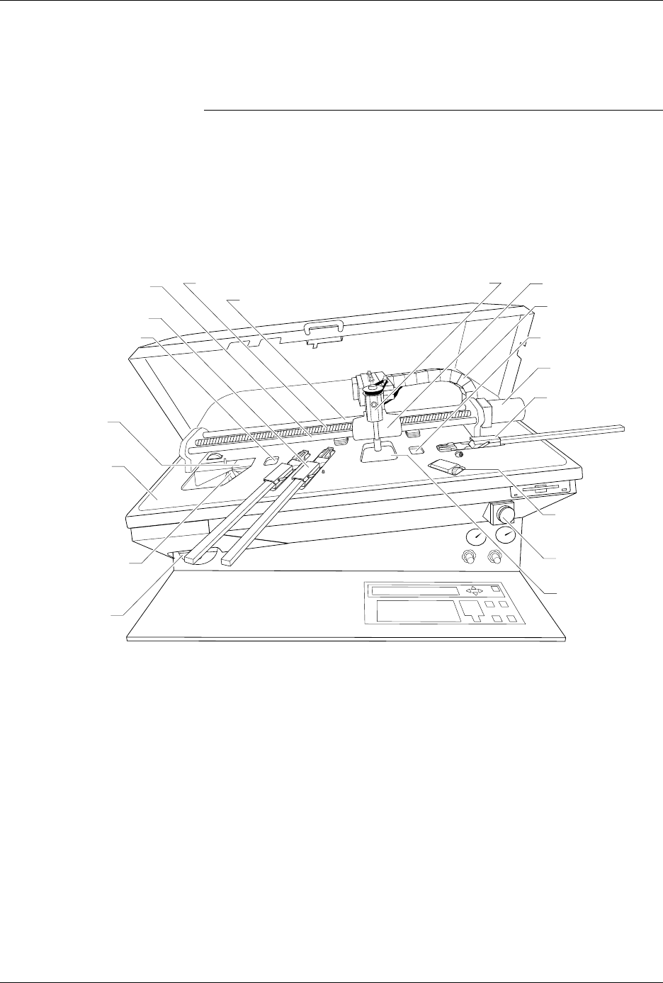
Lubricate the lead screw, beam shaft, and carriage shafts (see Figure 5-26)
approximately every three months or as needed.
CAUTION: This procedure should be performed only by a qualified
service technician or the system administrator.
1. Turn off the 2500 and remove the power cord.
2. With a clean cloth, wipe the lead screw and the front and rear beam
carriage shafts until no lubricant or dirt remains.
3. Move the beam to the center of the lead screw.
4. Apply four drops of TriFlow, evenly spaced, on each side of the lead
screw and one drop on each side of both beam carriage shafts.
5. Move the beam back and forth so the lubricant works into the screw
and shafts.
6. With a clean cloth, wipe excess lubricant from the sides of the lead
screw and shafts.
Figure 5-26
Location of the Lead Screw and the Carriage
1760-3
CABLE HARNESS
GUIDE
BEAM HEAD
BEAM TRAVERSE
MOTOR
INPUT TUBE
HOLDER
TRACK WIDTH
ADJUSTMENT
KNOB
REAR CARRIAGE SHAFT
LEAD SCREW
FRONT CARRIAGE SHAFT
OUTPUT TUBE
HOLDER (1 of 2)
BEAM CARRIAGE
MAIN PLATE
LABELER
LABEL
APPLICATION
AREA
DEVICE RECESS
(2 of 2)
DEVICE RECESS (1 of 2)
LABEL SUPPLY
REEL
PROGRAMMING
STATION
E-STOP
BUTTON
Preventive Maintenance
5-64 ProMaster 2500 User Manual
Track Adjustments
Adjusting Track
Height
You may have to adjust the track height to compensate for the varying
thickness of different device tubes. Use a 50-mil hex wrench to raise or
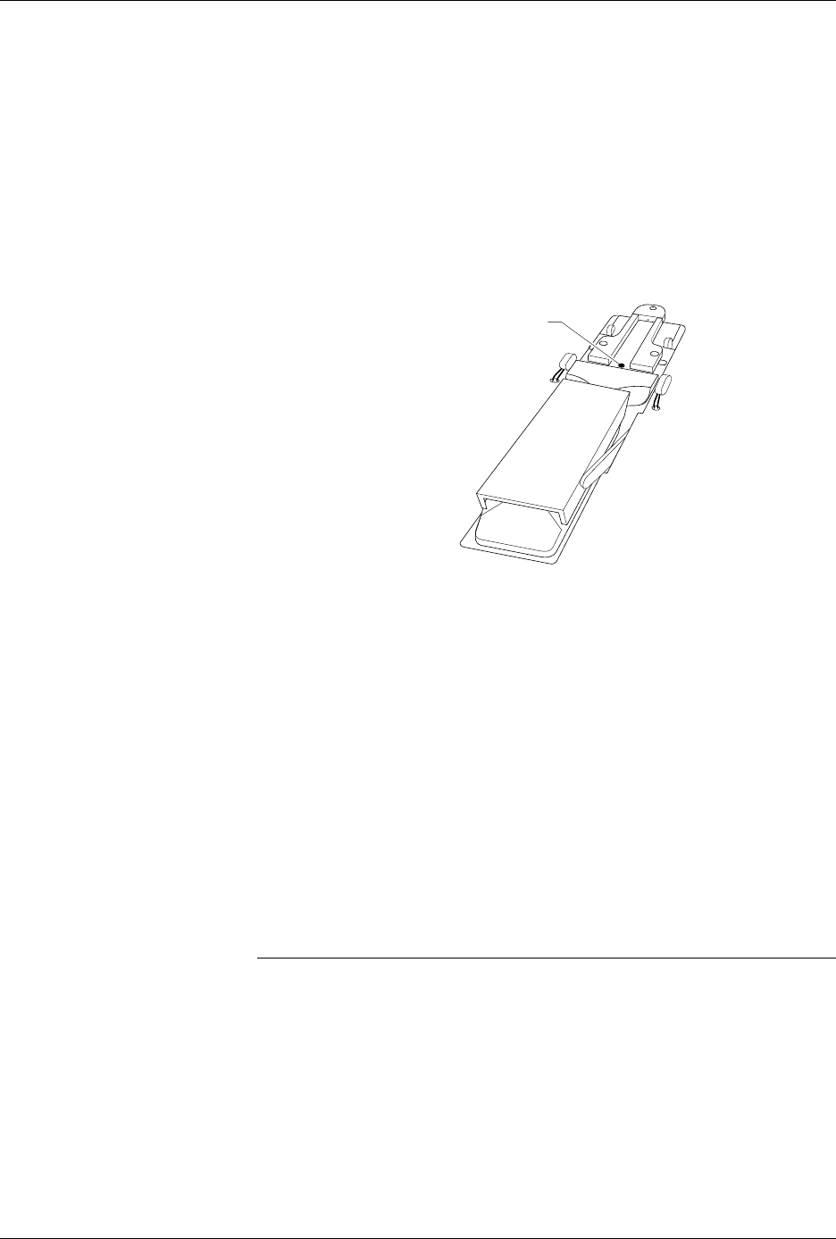
lower the height of the track. Follow the steps below.
1. Insert the 50-mil hex wrench into one of the track height adjustment
screws (see Figure 5-27).
2. Turn the track height adjustment screw clockwise to raise the track
height, or counterclockwise to lower the track height.
Adjusting the Angle of
the Track Walls
The entrance to the input track should be approximately 0.010 inch wider
than the pick-up point of the input track. The exit point of each output
track should be approximately 0.010 inch wider than the pick-up point of
the input track. If the 2500 is having difficulty picking up a device from
the input track or if devices flip up during operation, you may need to
perform a funnel adjustment.
To perform a funnel adjustment, follow the steps below.
1. Use a 3/32-inch hex wrench to loosen the set screws on the input
track front wall and rear wall.
2. Adjust each of the input track walls evenly to create a gap at the pick-
up point that is approximately 0.010 inch narrower than the entrance
to the input track.
Note: You may want to use a caliper to ensure that the gap at the pick-up point
is approximately 0.010 inch narrower than the gap at the entrance to the
input track.
3. When the input track is correctly adjusted, use a 3/32-inch hex
wrench to tighten the set screws on the input track front wall and rear
wall.
4. The output track funnel adjustment procedure is identical to the
input track procedure, except that the exit point of each output track
should be approximately 0.010 inch wider than the pick-up point of
the input track.
Figure 5-27
Adjusting the Track Height
2288-1
TRACK HEIGHT
ADJUSTMENT SCREW