2500_Users_Manual - 第245页
ProM aster 25 00 User Manua l 7-1 7 Repair and Replacement Procedures This chapter contains instructions fo r replacing failed components. These component replacement procedures should be perfo rmed by qualified service …
Troubleshooting
6-22 ProMaster 2500 User Manual
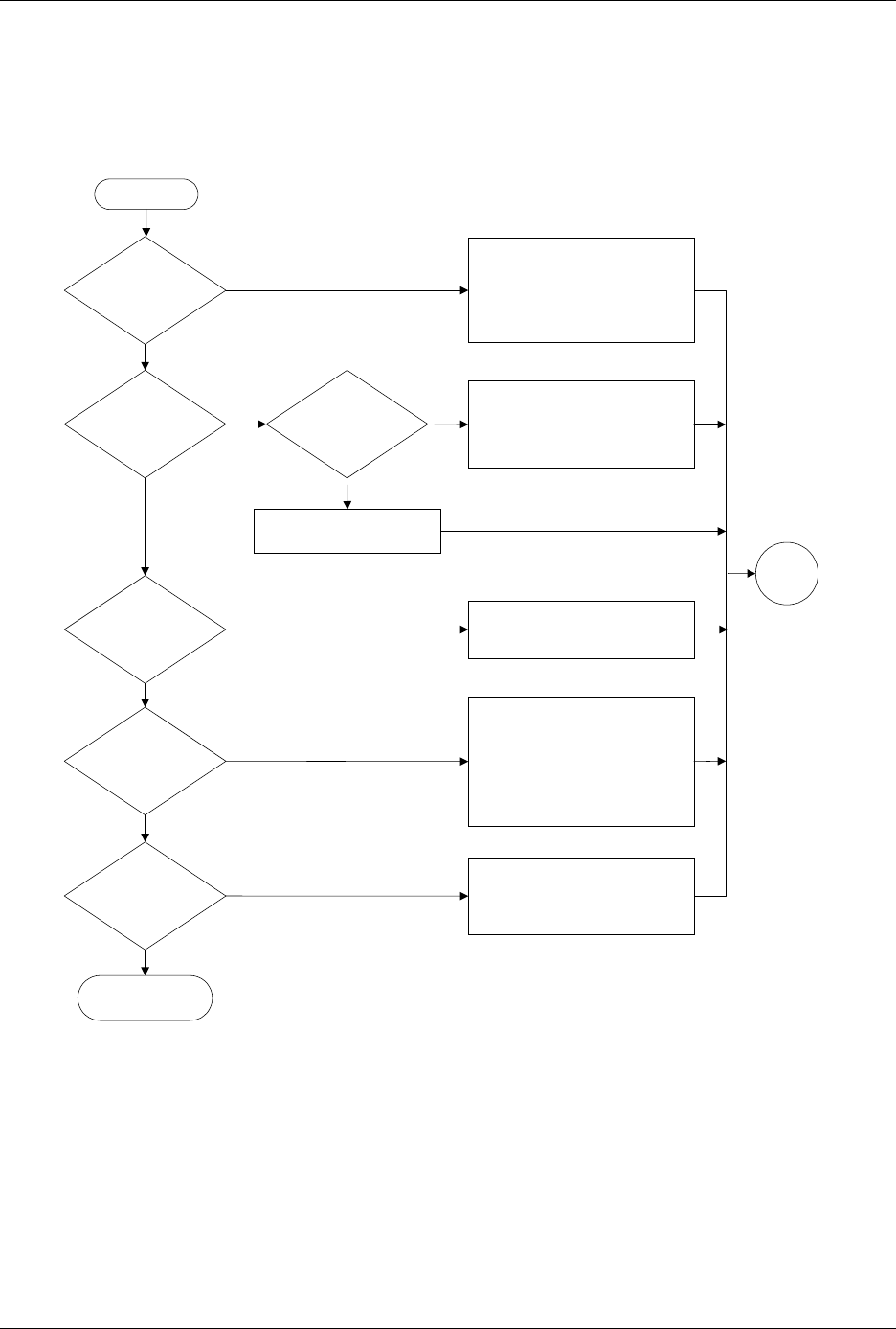
Figure 6-7
The Beam Does Not Deliver the Device Correctly (page numbers are in parentheses)
Does
beam release
devices?
Does the
device arrive at the
output track?
Does
beam lower to
output track
?
Does an
object block
beam?
Do
devices
move down
track?
Do devices
slide into output
tubes?
End
No
Yes
No
Yes
No
Yes
No
Yes
No
Yes
Clear the beam's vertical path
Yes
No
Check high air pressure (2-7)
Check vacuum generator (B-2)
Clean & chalk chuck tip (5-56)
Adjust track width (4-12)
Jog chuck position over track using
2500 keyboard arrow keys
Perform output track funnel
adjustment (5-64)
Adjust track air (4-38)
Check output orbital motor (5-40)
Check devices for label residue
Check for mechanical obstructions
Check +90V beam voltage (5-13)
Check flex coupler (7-21)
Clean & lubricate lead screw (5-63)
Reduce beam motor speed (B-3)
Check wiring & connectors
Check low pressure air (2-7)
Check beam up/down solenoid (5-38)
Check beam down optic test (5-32)
Clean & lubricate beam shafts (5-63)
Check wiring & connectors
Ensure that output tubes are correct
size, undamaged, & oriented correctly
Adjust track height (5-64)
Check devices for label residue
Start
Go to
Start

ProMaster 2500 User Manual 7-1
7
Repair and Replacement
Procedures
This chapter contains instructions for replacing failed components. These
component replacement procedures should be performed by qualified
service personnel only. Please refer to Chapter 6, “Troubleshooting,” to
determine which ProMaster 2500 component may be malfunctioning and
may require replacement. The flow chart in Chapter 6 will help you
identify a specific component failure and direct you to the appropriate
cleaning, adjustment, or replacement procedure.
The replacement procedures are divided into several sections and
presented in the following order:
Fuse Replacement....................................................................................7-2
Programming Electronics Assembly Replacement ............................7-3
Motor Replacement.................................................................................7-8
Mechanical Assembly Removal...........................................................7-16
Solenoid Replacement...........................................................................7-19
Power Supply Replacement.................................................................7-19
System Fan Replacement......................................................................7-21
Controller Board Replacement............................................................7-21
Beam Assembly Component Replacement........................................7-22
Disk Drive Replacement.......................................................................7-28
Keyboard/Display Assembly Replacement......................................7-29
Programmer Module Replacement.....................................................7-29
Assembly Drawings..............................................................................7-40
Repair and Replacement Procedures
7-2 ProMaster 2500 User Manual
Fuse Replacement
The main fuse is located behind the power cord input assembly. Perform
the following procedure to replace the main fuse.
CAUTION: For continued protection against the possibility of fire,
replace the blown fuse only with a fuse of the same voltage,
current, and type.
1. Turn off the 2500 and remove the power cord.
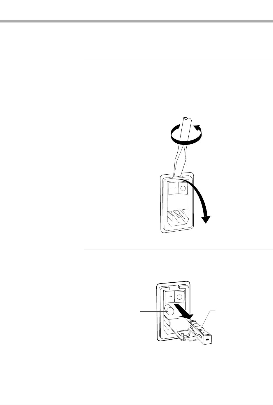
2. Use the edge of a flat-blade screwdriver to pry open the door
covering the fuse holder, as shown in Figure 7-1.
Note: Only the fuse in the fuse holder is connected to the circuitry. The fuse on
the left is a spare.
3. Pull the fuse holder out of its slot, as shown in Figure 7-2.
4. Determine if the fuse is intact. If it is blown, install a new fuse of the
same size and rating (5A SlowBlow for 100/120V systems and 3A
SlowBlow for 220/240V systems).
Figure 7-1
Opening the Power Input
Assembly to Access the Fuse
Figure 7-2
Removing the Fuse
1242-1
1243-1
SPARE FUSE FUSE HOLDER