2500_Users_Manual - 第246页
Repair and Repl acement Procedures 7-2 ProMa ster 25 00 U ser Ma nual Fuse Replaceme nt The main fuse is located behind th e power cord input assembly. Perf orm the following procedure to replace the main fuse. CAUTION: …

ProMaster 2500 User Manual 7-1
7
Repair and Replacement
Procedures
This chapter contains instructions for replacing failed components. These
component replacement procedures should be performed by qualified
service personnel only. Please refer to Chapter 6, “Troubleshooting,” to
determine which ProMaster 2500 component may be malfunctioning and
may require replacement. The flow chart in Chapter 6 will help you
identify a specific component failure and direct you to the appropriate
cleaning, adjustment, or replacement procedure.
The replacement procedures are divided into several sections and
presented in the following order:
Fuse Replacement....................................................................................7-2
Programming Electronics Assembly Replacement ............................7-3
Motor Replacement.................................................................................7-8
Mechanical Assembly Removal...........................................................7-16
Solenoid Replacement...........................................................................7-19
Power Supply Replacement.................................................................7-19
System Fan Replacement......................................................................7-21
Controller Board Replacement............................................................7-21
Beam Assembly Component Replacement........................................7-22
Disk Drive Replacement.......................................................................7-28
Keyboard/Display Assembly Replacement......................................7-29
Programmer Module Replacement.....................................................7-29
Assembly Drawings..............................................................................7-40
Repair and Replacement Procedures
7-2 ProMaster 2500 User Manual
Fuse Replacement
The main fuse is located behind the power cord input assembly. Perform
the following procedure to replace the main fuse.
CAUTION: For continued protection against the possibility of fire,
replace the blown fuse only with a fuse of the same voltage,
current, and type.
1. Turn off the 2500 and remove the power cord.
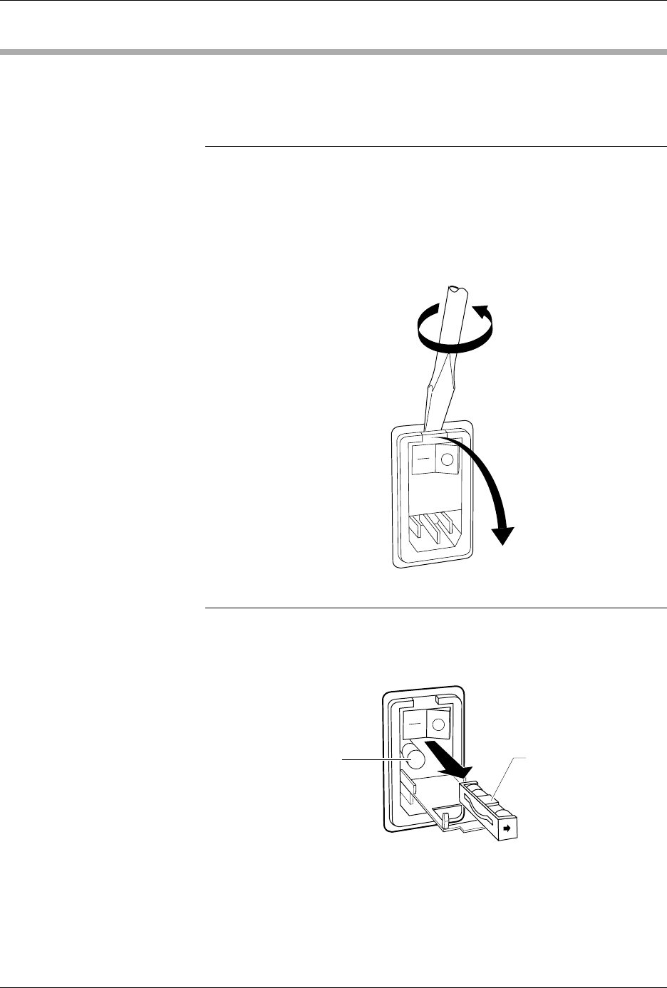
2. Use the edge of a flat-blade screwdriver to pry open the door
covering the fuse holder, as shown in Figure 7-1.
Note: Only the fuse in the fuse holder is connected to the circuitry. The fuse on
the left is a spare.
3. Pull the fuse holder out of its slot, as shown in Figure 7-2.
4. Determine if the fuse is intact. If it is blown, install a new fuse of the
same size and rating (5A SlowBlow for 100/120V systems and 3A
SlowBlow for 220/240V systems).
Figure 7-1
Opening the Power Input
Assembly to Access the Fuse
Figure 7-2
Removing the Fuse
1242-1
1243-1
SPARE FUSE FUSE HOLDER
Repair and Replacement Procedures
ProMaster 2500 User Manual 7-3
5. Insert the fuse holder into its slot with the arrow pointing in the same
direction as the arrows on the door and snap the door closed.
Programming Electronics Assembly Replacement
Removing the PE
Follow the steps below to remove the PE assembly from the 2500. The PE
assembly is mounted on the underside of the 2500’s main plate. You will
need to raise the main plate and use a 7/64-inch hex wrench to complete
the removal procedure.
WARNING:This procedure should be performed by a service
technician trained on electromechanical equipment. Do
not attempt this procedure unless you are qualified to do
so. Dangerous high voltages are generated under the main
plate that could cause a harmful electrical shock. Turn off
the 2500 before you begin this procedure.
To help eliminate damage from ESD, wear an antistatic
wrist strap that contains a 1M
Ω
(minimum) to 10M
Ω
(maximum) isolating resistor. The wrist strap should be
connected to the grounding plug.
1. Turn off the 2500 and remove the power cord.
2. Remove the programming module, if one is installed.
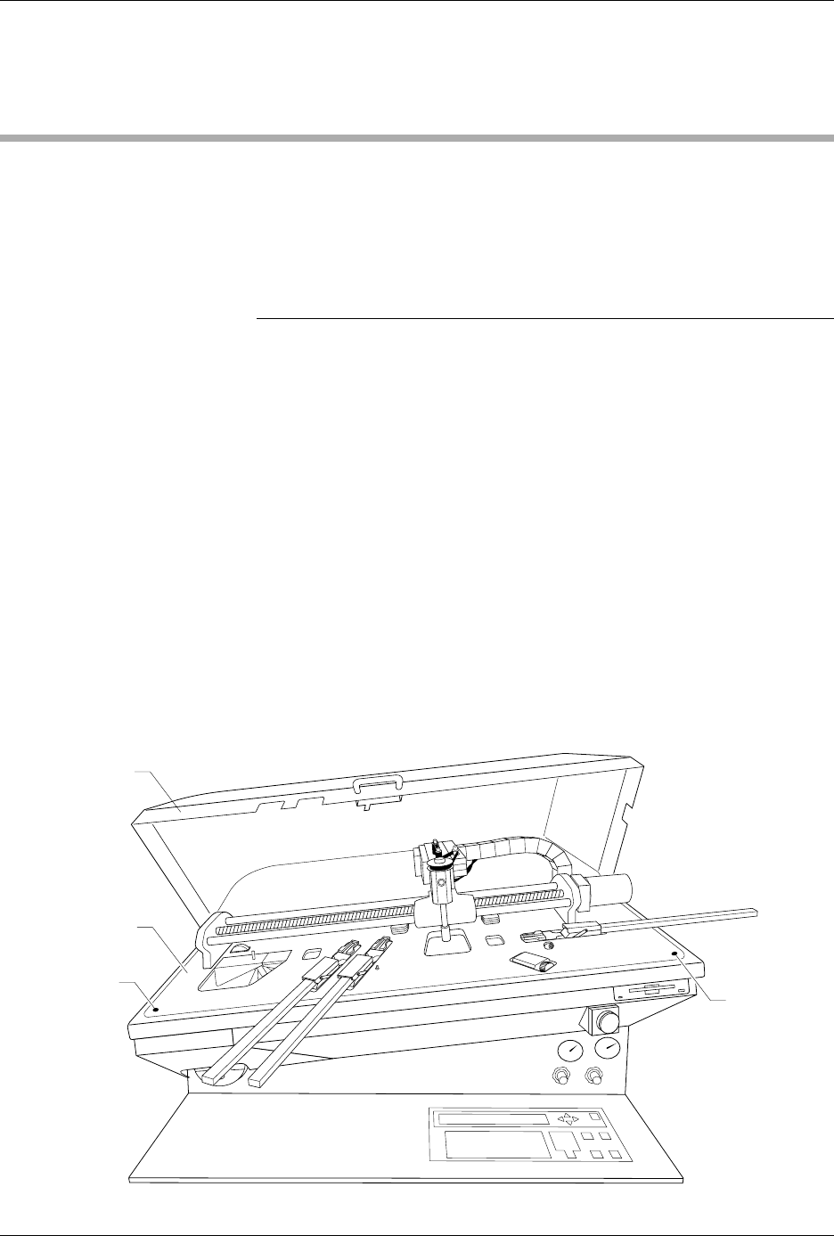
3. Unscrew the two captive hex screws located at the front corners of
the main plate (see Figure 7-3).
4. Lift the main plate until it stops in the fully upright position.
Figure 7-3
Location of the Main Plate Screws
2074-2
MAIN PLATE
MAIN PLATE
SCREW (1 of 2)
HOOD
MAIN PLATE
SCREW
(2 of 2)