2500_Users_Manual - 第251页
Repair and Repla cement Procedures ProM aster 25 00 User Manua l 7-7 14. Carefully slide the programming electronics assembly away from the clamp assembly. Figure 7-7 shows the two tracks on the clamp assembly tha t fit …
Repair and Replacement Procedures
7-6 ProMaster 2500 User Manual
10. Holding the programming electronics from the bottom, remove the
last two screws. Lower the programming module clamp assembly
and let it rest on the black protective shield.
Note: Hold the programming module clamp assembly in place (from below the
main plate) when you remove the assembly from the main plate.
11. Disconnect the two optic cables (S-24 and C-25).
Note: Before removing the air lines as described in the next step, mark the hoses
for proper reinstallation.
12. Remove the two blue and two red air lines from the four quick
connects on the programming module clamp assembly (see Figure
5-2).
13. Remove the retaining bar that holds the PE assembly in place on the
underside of the main plate (see Figure 7-6). Use a 7/64-inch hex
wrench to remove the two hex screws that hold the bar in place. Set
these in a safe place so you can use them to reinstall the PE assembly.
Figure 7-5
Remove the Module Clamp
Assembly Screws
2313-1
SCREW LOCATION (1 of 6)
Repair and Replacement Procedures
ProMaster 2500 User Manual 7-7
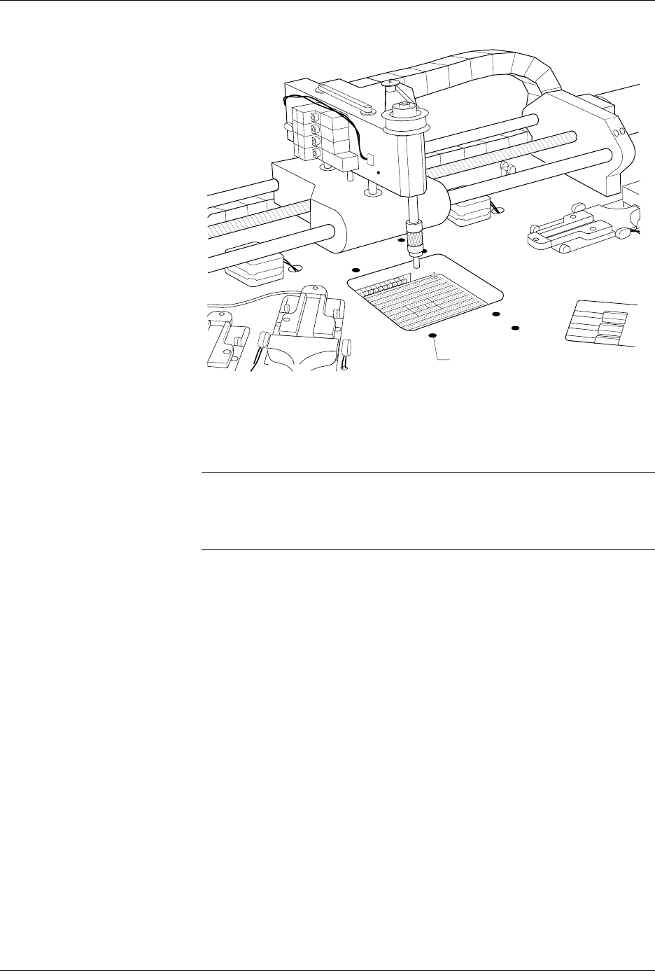
14. Carefully slide the programming electronics assembly away from the
clamp assembly. Figure 7-7 shows the two tracks on the clamp
assembly that fit into grooves on the pin block. The track and grooves
hold the assembly to the underside of the main plate. Do not twist the
programming electronics assembly as you slide it away from the
clamp assembly; doing so may damage the pin block.
15. Set the programming electronics assembly on an antistatic surface.
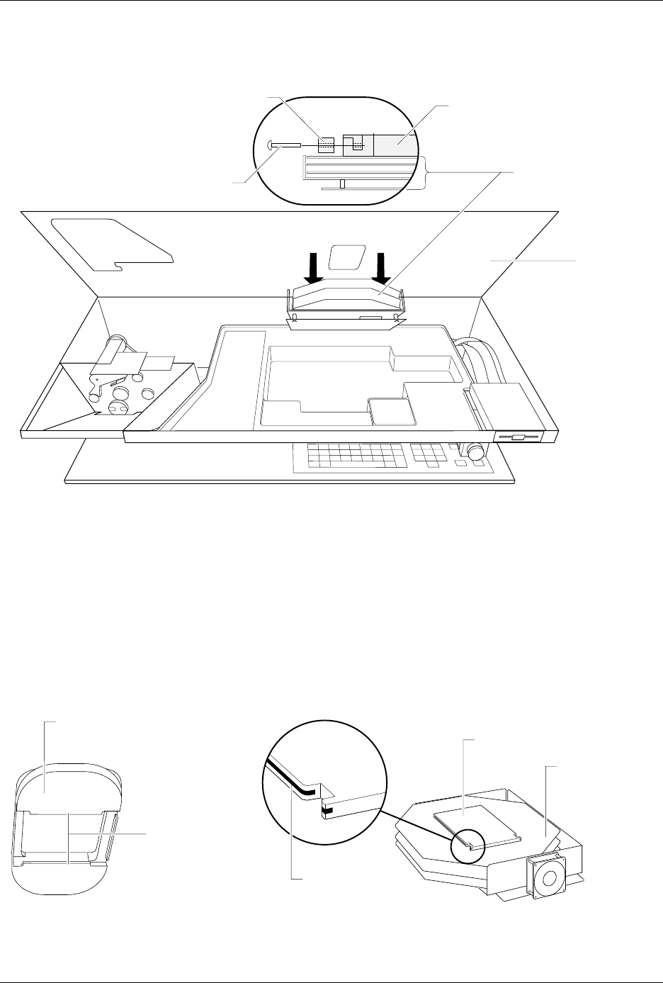
Figure 7-6
Lower the Clamp Assembly and Remove the Retaining Bar
Figure 7-7
Programming Electronics Assembly Alignment
2070-2
MAIN PLATE
(Underside)
PROGRAMMING
ELECTRONICS
ASSEMBLY
PROGRAMMING MODULE
CLAMP ASSEMBLY
HEX HEAD SCREW
RETAINING BAR
A
J
S
SHIFT
B
K
T
DEL
C
L
U
D
M
V
E
N
W
F
O
X
SHIFT
G
P
Y
H
Q
Z
I
R
ENTER
1
4
7
2
5
8
3
6
9
0
LOW
CASE
RESET
STOP
CAL
START
2066-2
GROOVE
TRACKS
PIN BLOCK
PROGRAMMING
ELECTRONICS
ASSEMBLY
BOTTOM SIDE OF PROGRAMMING
MODULE CLAMP ASSEMBLY

Repair and Replacement Procedures
7-8 ProMaster 2500 User Manual
Installing the PE
Assembly
Follow the steps below to install the programming electronics assembly
in the 2500.
1. Turn off the 2500 and remove the power cord.
CAUTION: Pins in the pin block are delicate and could be damaged if
they hit components mounted on the underside of the main
plate. The pin block cover ensures that these pins are not
damaged while you are removing or reinstalling the PE
assembly.
2. Carefully slide the PE assembly onto the clamp assembly. Figure 7-7
shows the two tracks on the clamp assembly that fit into grooves on
the pin block.
3. Install the retaining bar and its two hex screws to connect the PE
assembly to the clamp assembly.
4. Reconnect the two optic cables (S-24 and C-25).
5. Reconnect the two of the four air lines (one red and one blue) to the
rear quick connects.
6. Hold the programming module clamp assembly in place and reinstall
the six 7/64-inch hex screws.
7. Reconnect the two remaining air lines (one red and one blue) to the
front quick connects.
8. Reconnect all of the remaining cables.
CAUTION: When you connect the cables, be careful to use the correct
polarity of the cables to the connectors. Reversing or
misaligning a cable could damage components on the 2500.
9. Connect the 2500 to a compressed air source and check for air leaks
by listening for a hissing sound.
10. When you determine that there aren’t any air leaks, lower the main
plate.
11. Tighten the two corner screws in the main plate (see Figure 7-3).
Motor Replacement
These procedures explain how to replace any motor that may have failed.
Replacing the Input
Orbital Motor
Follow these steps below to access and replace the input orbital motor.
1. Turn off the 2500 and remove the power cord.
2. Remove the PE assembly, as described on page 7-3.
3. Locate the round input orbital motor collar. Loosen the 7/64-inch hex
screw and remove the motor collar.