2500_Users_Manual - 第267页
Repair and Repla cement Procedures ProM aster 25 00 User Manua l 7-23 6. Re inst all the tr aver se motor and attac h the new flex co uple r to th e lead screw. Tighten with a torqu e wrench and a left-side screw using 2…

Repair and Replacement Procedures
7-22 ProMaster 2500 User Manual
CAUTION: Cover the power supply assemblies in the base of the 2500
with a large sheet of paper to catch any mounting hardware
(screws, washers, and nuts) that might otherwise fall onto
the power supply assemblies as you work. If a piece of
mounting hardware is not accounted for when you install
the new controller board, do not turn on the 2500 until you
have located the missing piece of mounting hardware. If a
screw, washer, or nut contacts one of the 2500’s base
assemblies, an electrical short could occur when you turn on
the 2500, resulting in severe damage to the 2500.
4. Use a 1/4-inch hex nut driver to remove the ten nuts holding the
controller board to the front inner wall of the base of the 2500.
5. Lift the controller board straight up.
Note: Each of the mounting screws under the controller board has a nylon spacer
on it. Do not remove these spacers from the mounting studs.
6. Place the controller board on an antistatic mat or bag.
7. Transfer the firmware from U15 and U43 (unless new firmware is
specifically issued), as well as the U16 EEPROM, to the new
controller board.
8. Install the new controller board.
Note: Refer to the controller board wiring diagram in Appendix C.
Beam Assembly Component Replacement
These procedures describe the steps required to remove and replace the
beam assembly components.
Replacing the Flex
Coupler
If the flex coupler is damaged, follow the steps below to replace it.
1. Turn off the 2500 and remove the power cord.
2. Remove the beam traverse motor as described on page 7-15, but do
not remove the cables.
3. Use a 7/64-inch hex wrench to remove the set screw on the left side of
the flex coupler. (The flex coupler is attached to the end of the lead
screw.)
4. Remove the flex coupler.
5. Attach the new flex coupler to the beam traverse motor shaft. Tighten
with a torque wrench and a right-side screw using 24 inch-pounds of
torque.
CAUTION: Over-tightening the set screw can damage the flex coupler.
Repair and Replacement Procedures
ProMaster 2500 User Manual 7-23
6. Reinstall the traverse motor and attach the new flex coupler to the
lead screw. Tighten with a torque wrench and a left-side screw using
24 inch-pounds of torque.
Note: After you have reinstalled the flex coupler, make sure it does not drag on
the enclosed (right) side of the bracket. Leave a 1/8-inch clearance
(approximately).
Replacing the Right
Lead Screw Bearing
Assembly
If the right lead screw bearing assembly fails, follow the steps below to
replace it.
1. Turn off the 2500 and remove the power cord.
Note: This procedure requires two people to perform the steps safely.
2. Slide the beam over the programming station.
3. Remove the beam traverse motor as described on page 7-15.
4. Use a 1/8-inch hex wrench to remove the four screws in the bearing
cover plate on the right end plate.
5. Use a 9/64-inch hex wrench to loosen the four hex screws holding the
front and rear carriage shafts to the right end plate.
Note: Have an assistant hold the lead screw and shafts during the next steps.
6. Loosen the two main plate corner screws and lift the main plate.
7. Use a hex wrench to remove the two screws holding the right end
plate to the main plate.
8. Lower the main plate and slide the end plate off the shafts and lead
screw.
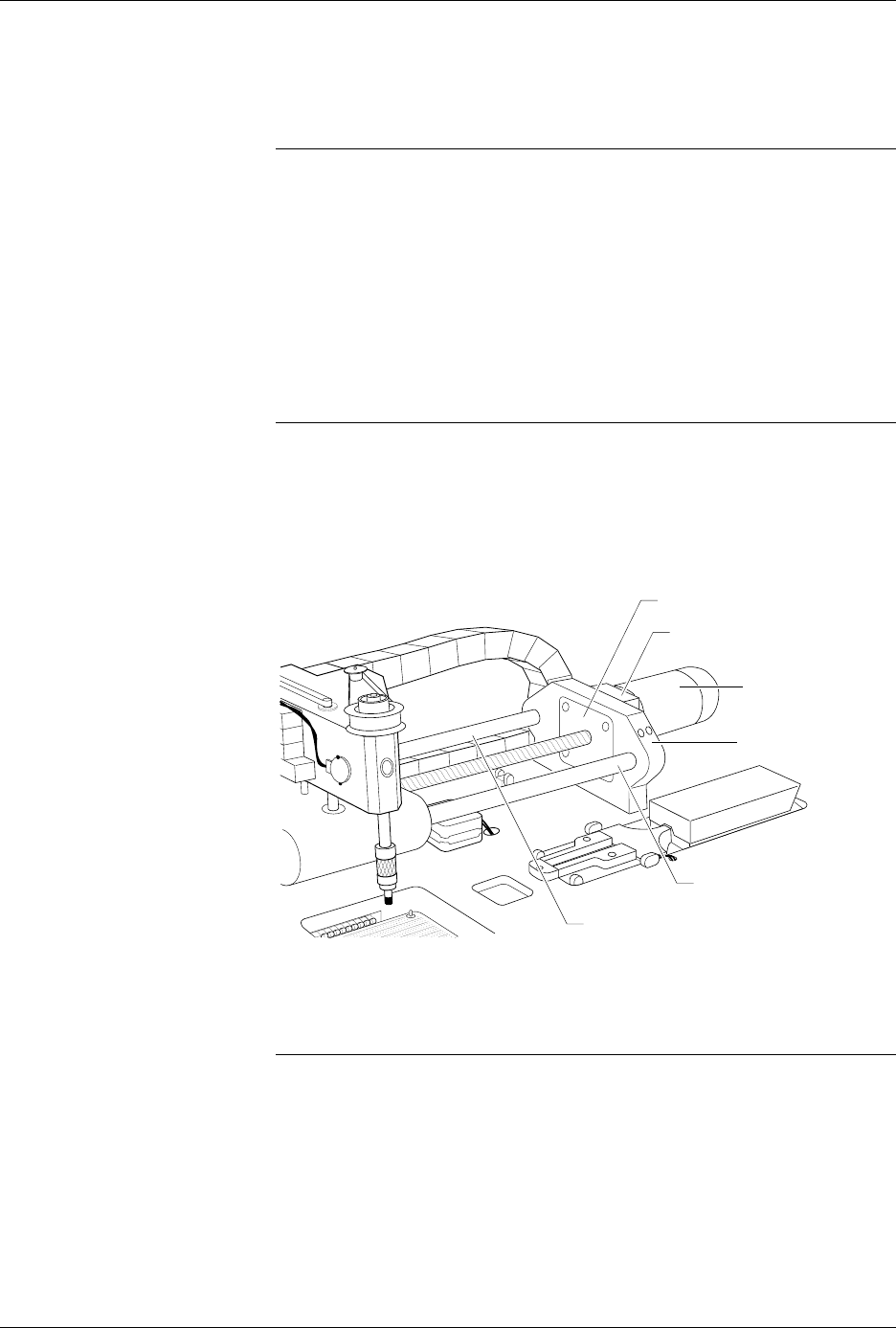
Figure 7-16
Right Lead Screw Bearing
Assembly
2389-1
BEAM TRAVERSE
MOUNTING BLOCK
RIGHT END PLATE
BEARING COVER PLATE
BEAM TRAVERSE
MOTOR
REAR CARRIAGE SHAFT
FRONT COVER SHAFT

Repair and Replacement Procedures
7-24 ProMaster 2500 User Manual
9. The right lead screw bearing assembly will come away from the right
end plate with the lead screw. Remove the bearing assembly and
replace it with a new bearing assembly.
10. Reverse the procedure to reinstall all of the components.
Replacing the Left
Lead Screw Bearing
Assembly
If the left lead screw bearing assembly fails, follow the steps below to
replace it.
1. Turn off the 2500 and remove the power cord.
Note: This procedure requires two people to perform the steps safely.
2. Slide the beam over the programming station.
3. Use a 1/8-inch hex wrench to remove the four screws in the bearing
cover plate on the left end plate.
4. Use a 9/64-inch hex wrench to loosen the four hex screws holding the
front and rear carriage shafts to the left end plate.
Note: Have an assistant hold the lead screw and shafts during the next steps.
5. Loosen the two main plate corner screws and lift the main plate.
6. Use a hex wrench to remove the two screws holding the left end plate
to the main plate.
7. Lower the main plate and slide the end plate off the shafts and lead
screw.
8. The left lead screw bearing assembly will come away from the left
end plate with the lead screw. Remove the bearing assembly and
replace it with a new bearing assembly.
9. Reverse the procedure to reinstall all of the components.
Replacing the Lead
Screw
If the lead screw is damaged, follow the steps below to replace it.
1. Turn off the 2500 and remove the power cord.
2. Slide the beam over the programming station.
Note: This procedure requires two people to perform the steps safely.
3. Look through the two holes in the top of the beam traverse motor’s
mounting block while you manually rotate the lead screw until the
heads of the flex coupler set screws are visible through the holes.
4. Use a 7/64-inch hex wrench to remove the set screw on the left side of
the flex coupler.
5. Use a 1/8-inch hex wrench to remove the four screws in the bearing
cover plate on the left end plate.