2500_Users_Manual - 第271页
Repair and Repla cement Procedures ProM aster 25 00 User Manua l 7-27 10. Use a 6/64-in ch hex wrench to remove the tw o screws that h old the air cylinder pin in pl ace. 11. Hold the bea m in place while you us e a 3/32…

Repair and Replacement Procedures
7-26 ProMaster 2500 User Manual
9. Apply a small amount of purple Loctite on the outer surface of the
new nut where it contacts the carriage during operation.
10. Twist the new anti-backlash nut into place and carefully re-assemble
all of the disconnected components.
Replacing the Beam
Gasket
If there are air leaks in the beam, follow the steps below to replace the
beam air channel gasket.
1. Turn off the 2500, remove the power cord, and disconnect the air
supply.
2. Disconnect the vacuum sensor cable from the vacuum sensor switch.
3. Disconnect the four solenoid cables.
4. Use a 3/32-inch hex wrench to remove the solenoid cable connector.
5. Disconnect the beam head rotation motor cable.
6. Disconnect the three optic cables.
Note: Write down the cable positions before you cut the tie wraps that hold the
cables in place.
7. Use a 1/8-inch hex wrench to remove the two screws that hold the
cable harness to the right side of the beam.
8. Disconnect the gray air line and the black vacuum line from the two
quick connects, noting their location.
9. Use a 5/64-inch hex wrench to remove the two screws that hold the
limit bar to the beam shafts (see Figure 7-17).
Repair and Replacement Procedures
ProMaster 2500 User Manual 7-27
10. Use a 6/64-inch hex wrench to remove the two screws that hold the
air cylinder pin in place.
11. Hold the beam in place while you use a 3/32-inch hex wrench to
gently push the air cylinder pin through the beam.
12. Gently lift the beam up and away from the beam shafts.
13. Remove the two 1/16-inch set screws in the beam motor drive pulley.
14. Disconnect the beam motor cable.
15. Remove the single 3/32-inch hex mounting screw in the beam head
pulley.
16. Pull up the beam head pulley and remove the beam rotation belt.
17. Remove the motor drive pulley.
18. Use a 1/16-inch hex wrench to remove the four motor mounting
screws, then remove the beam head rotation motor.
19. Use a 3/32-inch hex wrench to remove the two air quick connects
(insert the hex wrench into the quick connect openings).
20. Use a 3/32-inch hex wrench to remove 20 screws in the baffle plate.
21. Use a 1/4-inch hex wrench to remove the three remaining pan head
screws in the baffle plate.
22. Peel off the old air channel gasket.
23. Place the new air channel gasket onto the baffle plate.
Note: Make sure the air channel gasket does not block any air and vacuum holes.
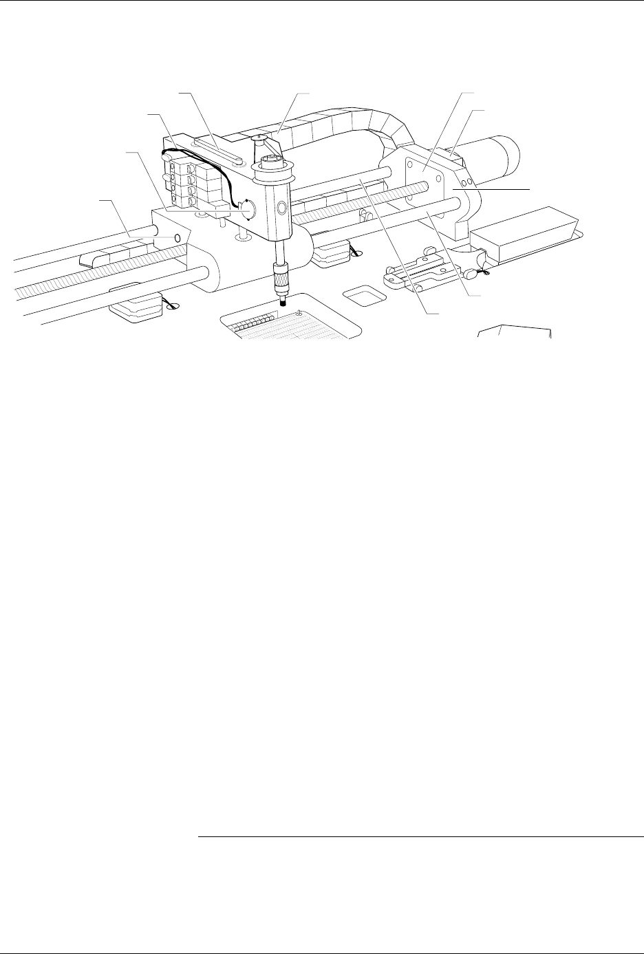
Figure 7-17
Beam Cable and Switch Locations
2287-1
VACUUM SENSOR CABLE
CABLE HARNESS GUIDE
BEAM TRAVERSE
MOUNTING BLOCK
RIGHT END PLATE
LIMIT BAR
BEARING COVER PLATE
REAR CARRIAGE SHAFT
FRONT COVER SHAFT
VACUUM SENSOR
SWITCH
AIR CYLINDER
PIN SCREW
(1 on each side)
Repair and Replacement Procedures
7-28 ProMaster 2500 User Manual
24. Place the baffle plate back on the beam and then reinstall all of the
screws in the order shown in Figure 7-18.
25. Carefully re-assemble all of the disconnected cables and components.
Disk Drive Replacement
This procedure describes the steps required to remove and replace the
disk drive.
Replacing the Disk
Drive
If the disk drive fails, follow the steps below to replace it.
1. Turn off the 2500 and remove the power cord.
2. Disconnect the disk drive power cable.
3. Disconnect the disk drive ribbon cable.
4. Use a 3/32-inch hex wrench to remove the two screws from under
the disk drive mounting plate. Remove the disk drive.
5. Use a 3/32-inch hex wrench to attach the new disk drive to the disk
drive mounting plate and reconnect the power and ribbon cables.
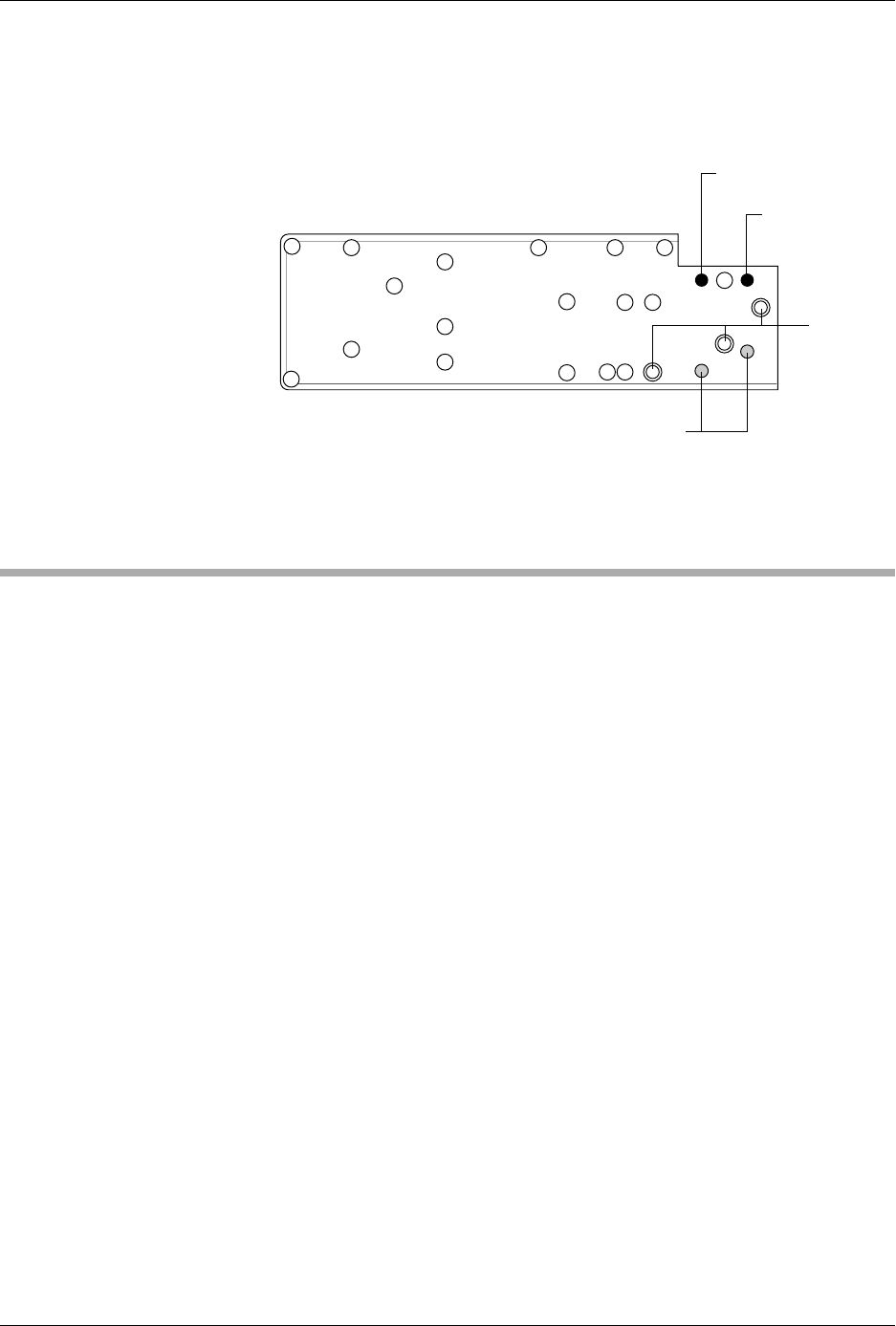
Figure 7-18
Baffle Plate Reinstallation
LO QUICK
CONNECT
(Gray)
HI QUICK
CONNECT (Black)
E CHAIN SCREWS
2338-1
1/4"
SCREWS
1
11
15 5 8 13
19
21
17
1274
6910
16
3
2
14
18
20
22
23