2500_Users_Manual - 第274页
Repair and Repl acement Procedures 7-30 ProMa ster 25 00 U ser Ma nual 3. Turn the module so the underside is facing you. 4. Use a 1/ 16-inch he x wrench to remove the tw o screws (on the si des of the module) that h old…

Repair and Replacement Procedures
ProMaster 2500 User Manual 7-29
Keyboard/Display Assembly Replacement
This procedure describes the steps required to remove and replace the
keyboard/display assembly.
Replacing the
Keyboard/Display
Assembly
If the keyboard/display assembly fails, follow the steps below to replace
it.
1. Turn off the 2500 and remove the power cord.
2. Use the flat edge of a flat-head screwdriver (or a table knife) to pry up
the bottom left and top sides of the keyboard/display assembly,
which is affixed with two-sided tape.
CAUTION: Do not pry up the right side of the display.
3. Pull the keyboard/display assembly away from the 2500.
Note: The keyboard/display assembly is held in place with double-sided tape.
4. Remove the two cables that connect the keyboard/display assembly
to the controller board.
5. Apply double-sided tape to the underside of the new keyboard/
display assembly.
6. Connect the two controller board cables to the new keyboard/display
assembly.
7. Press the new keyboard/display assembly into place.
Programming Module Components Replacement
These procedures describe the steps required to replace failed
components on programming modules.
Replacing Contacts
on a DIP Module
Use the following procedure to replace the contact sets on a
programming module. Replace both sides at the same time.
1. Mark the module on the end next to the narrower end of the circuit
board. You must reinstall the module on the board in the correct
orientation. It is possible to reinstall the module backwards on the
board.
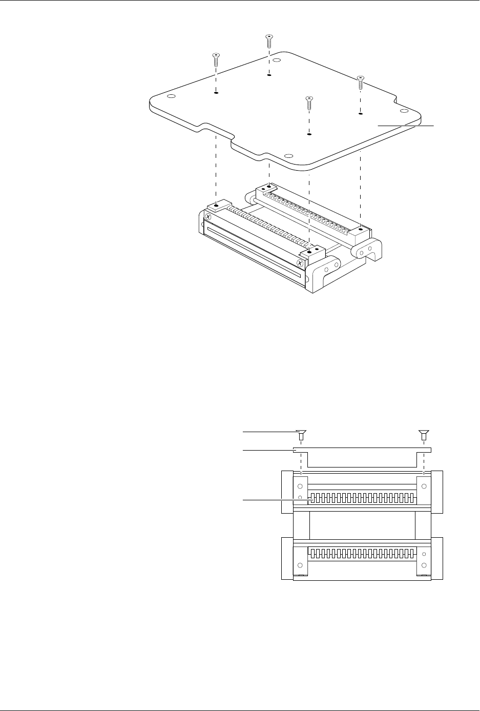
2. Remove the four hex screws from the underside of the programming
module board and remove the printed circuit board (see Figure 7-19).
Repair and Replacement Procedures
7-30 ProMaster 2500 User Manual
3. Turn the module so the underside is facing you.
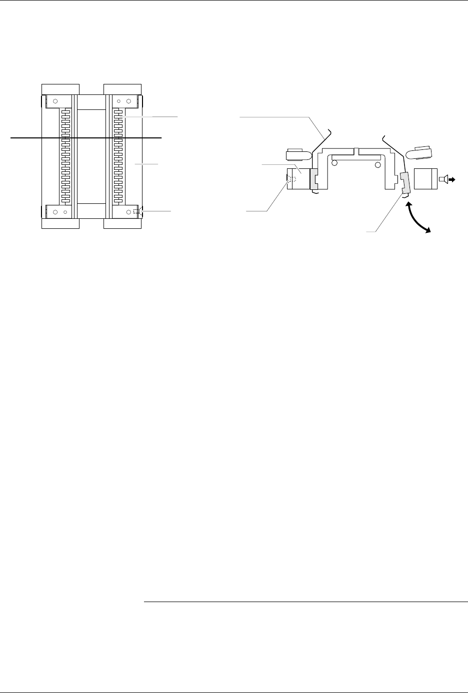
4. Use a 1/16-inch hex wrench to remove the two screws (on the sides of
the module) that hold the retaining block in place (see Figure 7-20).
Remove the retaining bar and set it aside.
5. Hold the black plastic base of the contact and gently remove the set
through the underside of the module (see Figure 7-21). Do not
remove the set through the top of the module.
Figure 7-19
Removing the DIP Module from the
Circuit Board
Figure 7-20
Removing the Retaining Block
1927-1
PRINTED
CIRCUIT
BOARD
1928-1
SCREW
RETAINING BLOCK
CONTACT SET
Repair and Replacement Procedures
ProMaster 2500 User Manual 7-31
6. Gently feed the new contact set through the underside of the module
into its operating position. The contact set has a notch that fits the
ridge in the module to set the correct alignment. Confirm that these
two are seated before proceeding.
7. Set the retaining bar in position on the contact set, and use the two
screws to hold the bar in place.
8. Insert the contact set on the other side, and tighten its retaining
screws.
9. Reinstall the programming module on the circuit board, observing
the correct orientation as you noted in the first step.
Replacing Contacts
on a PLCC Module
When contacts fail because of a high number of insertions, they generally
exhibit a gradual, progressive increase in programming failures over
several days or weeks. Sudden onset of a high programming failure rate
is usually an indication of some other problem and not a sign of worn
contacts.
One method of keeping track of the number of devices programmed is to
use TaskLink’s Session Data Logging feature (see page 3-19). When
enabled, this option maintains a log of all TaskLink operations and
continuously updates the statistics in a file on your PC. One of the
categories recorded is a count of the number of devices processed during
each Task run. These statistics allow you to calculate the number of
insertions for each device type.
CAUTION: To avoid possible damage to the system components, this
procedure should be performed only by a qualified service
technician.
Figure 7-21
Removing or installing the Contact Set
1929-1
CONTACT SET
RETAINING BLOCK (1 of 2)
SCREW (2 per side)
VIEW FROM BELOW
CROSS SECTION
CROSS SECTION PLANE
TILT CONTACT SET BEFORE
REMOVING OR INSERTING