2500_Users_Manual - 第275页
Repair and Repla cement Procedures ProM aster 25 00 User Manua l 7-31 6. Gently feed the new contact set through the underside of the m odule into its operat ing position . The contact set ha s a notch tha t fits the rid…
Repair and Replacement Procedures
7-30 ProMaster 2500 User Manual
3. Turn the module so the underside is facing you.
4. Use a 1/16-inch hex wrench to remove the two screws (on the sides of
the module) that hold the retaining block in place (see Figure 7-20).
Remove the retaining bar and set it aside.
5. Hold the black plastic base of the contact and gently remove the set
through the underside of the module (see Figure 7-21). Do not
remove the set through the top of the module.
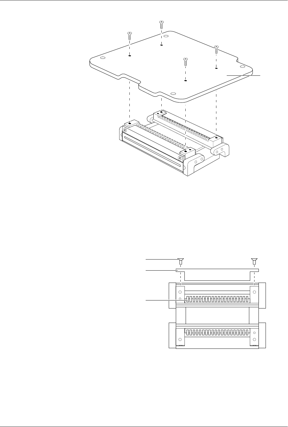
Figure 7-19
Removing the DIP Module from the
Circuit Board
Figure 7-20
Removing the Retaining Block
1927-1
PRINTED
CIRCUIT
BOARD
1928-1
SCREW
RETAINING BLOCK
CONTACT SET
Repair and Replacement Procedures
ProMaster 2500 User Manual 7-31
6. Gently feed the new contact set through the underside of the module
into its operating position. The contact set has a notch that fits the
ridge in the module to set the correct alignment. Confirm that these
two are seated before proceeding.
7. Set the retaining bar in position on the contact set, and use the two
screws to hold the bar in place.
8. Insert the contact set on the other side, and tighten its retaining
screws.
9. Reinstall the programming module on the circuit board, observing
the correct orientation as you noted in the first step.
Replacing Contacts
on a PLCC Module
When contacts fail because of a high number of insertions, they generally
exhibit a gradual, progressive increase in programming failures over
several days or weeks. Sudden onset of a high programming failure rate
is usually an indication of some other problem and not a sign of worn
contacts.
One method of keeping track of the number of devices programmed is to
use TaskLink’s Session Data Logging feature (see page 3-19). When
enabled, this option maintains a log of all TaskLink operations and
continuously updates the statistics in a file on your PC. One of the
categories recorded is a count of the number of devices processed during
each Task run. These statistics allow you to calculate the number of
insertions for each device type.
CAUTION: To avoid possible damage to the system components, this
procedure should be performed only by a qualified service
technician.
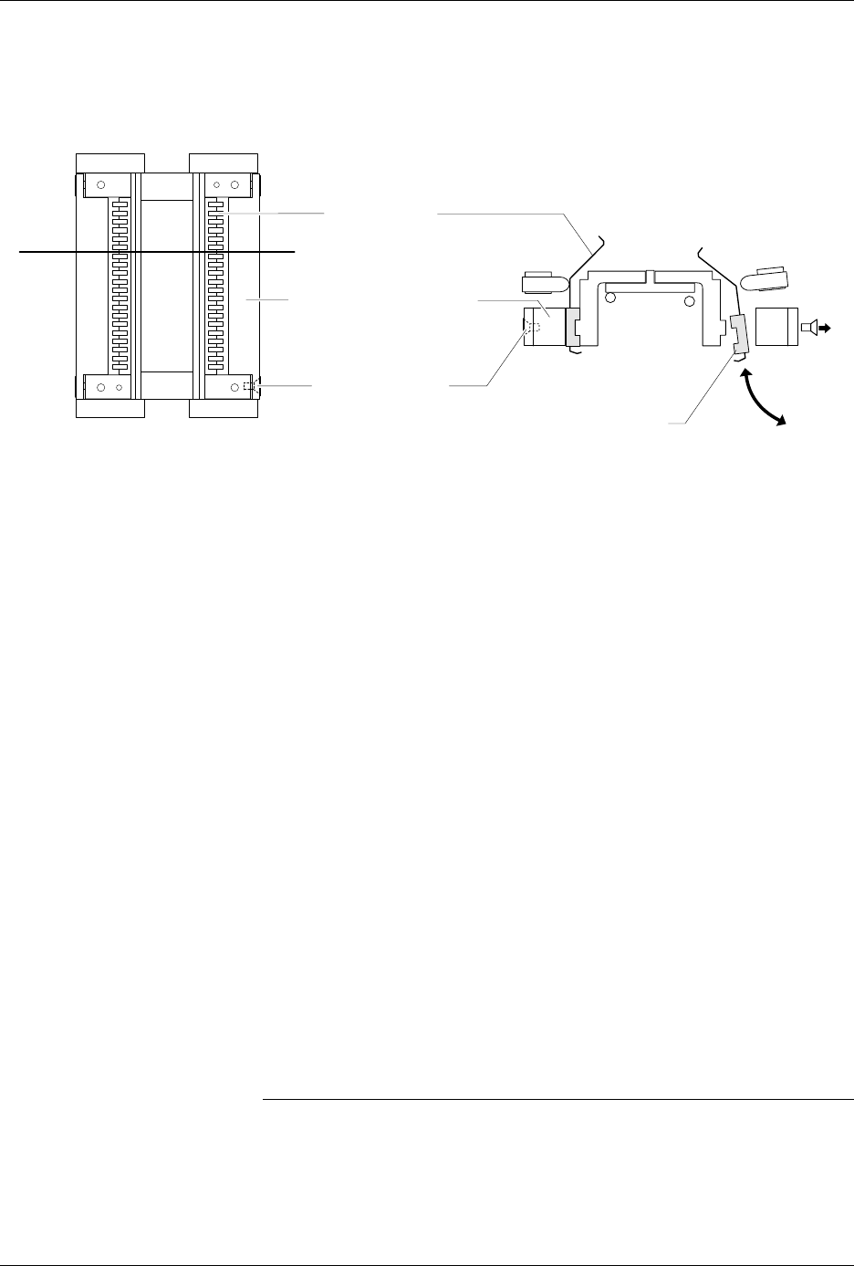
Figure 7-21
Removing or installing the Contact Set
1929-1
CONTACT SET
RETAINING BLOCK (1 of 2)
SCREW (2 per side)
VIEW FROM BELOW
CROSS SECTION
CROSS SECTION PLANE
TILT CONTACT SET BEFORE
REMOVING OR INSERTING
Repair and Replacement Procedures
7-32 ProMaster 2500 User Manual
When you have determined that the contacts need replacing, perform the
operations described in the steps below. You will need the following
items to complete this procedure:
• 1/16-inch hex driver
• 0.050-inch hex driver
• Four new contact sets
1. Remove the configuration blocks from all four sides (see Figure 7-22).
2. Turn the board upside down. Use the 0.050-inch hex driver to
remove the two screws holding the programming block to the circuit
board. Be careful not to strip the screws.
3. Keep the module in the upside-down position and gently pull the
board from the programming block assembly (see Figure 7-23).
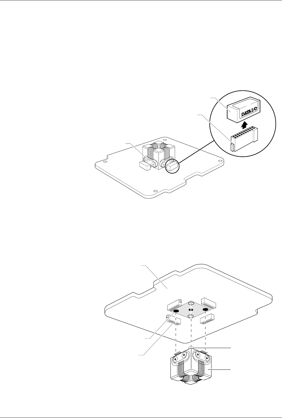
Figure 7-22
Removing the Configuration Blocks
Figure 7-23
Removing the Programming Block
1649-1
CONFIGURATION BLOCK
CONFIGURATION CONNECTOR
CONTACT SET
(1 of 4)
20A
1X
4X
BLOCK ALIGNMENT
PIN (1 of 2)
PROGRAMMING
BLOCK ASSEMBLY
CIRCUIT BOARD
SCREW HOLE (1 of 2)
CONFIGURATION
CONNECTOR (1 of 4)
1669-2