2500_Users_Manual - 第31页
Intr oduc tion Pro Master 25 00 User Manu al 3/97 1-9 Figure 1-7 Beams and Programming Stat ion Component Identification Drawing BEAM HOME OPTIC 1766-1 BEAM ROTATE MOTOR BEAM SOLENOID (1 of 4) BEAM DOWN OPTIC BEAM UP OPT…
Introduction
1-8 3/97 ProMaster 2500 User Manual
.
Label Application Area
—The portion of the labeler where a printed
label is applied to the device.
Track Height Adjustment
—A hex screw allows the operator to adjust
the height of the track section to match the height of the input and output
tubes (see Figure 1-7).
Optics
—These emitter-collector pairs detect passing devices as they
travel through the system. The 2500 uses the optics to keep track of
devices entering from the input, count devices passing into the output
tubes, detect device jams if they occur, and perform other operations. A
special optic pair on the labeler (called the ADC optic) is used to sense the
location of the labels on the roll.
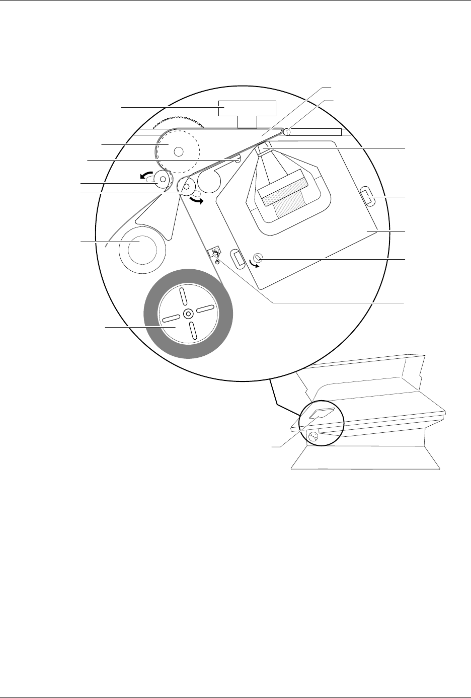
Figure 1-6
Dot Matrix Labeler Component Identification Drawing
1770-2
LABELING STATION
PRINT HEAD
SPRING CLIP
(1 of 2)
RIBBON
ADVANCE
KNOB
RIBBON
CASSETTE
PRESS BEARINGS
PLATEN
APPLICATION PLATE (Raised)
LABEL DRIVER ROLLER
PINCH ROLLER 2
PINCH ROLLER 1
LABEL ADVANCE
KNOB
LABEL REEL COVER
LABEL
SENSING
OPTIC
ADC OPTIC (1 of 2)
Introduction
ProMaster 2500 User Manual 3/97 1-9
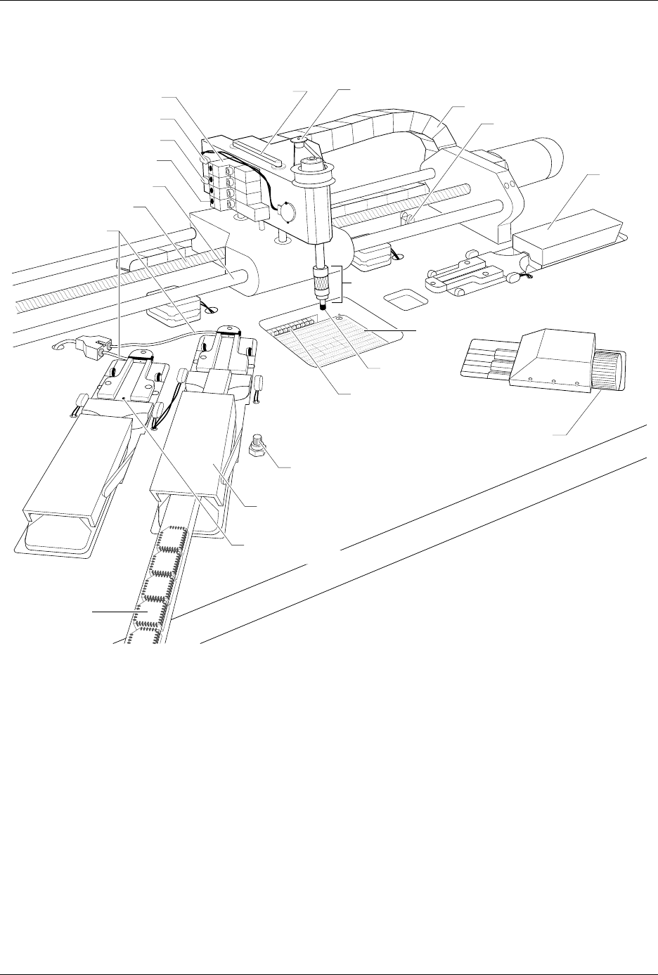
Figure 1-7
Beams and Programming Station Component Identification Drawing
BEAM HOME OPTIC
1766-1
BEAM ROTATE MOTOR
BEAM SOLENOID (1 of 4)
BEAM DOWN OPTIC
BEAM UP OPTIC
SOLENOID LED (1 of 4)
CHUCK
CABLE HARNESS GUIDE
INPUT
TUBE
HOLDER
TRACK WIDTH
ADJUSTMENT KNOB
MODULE CLAMP
(1 of 2)
TRACK AIR ADJUSTMENT KNOB
CHUCK TIP
SPA PINS
DEVICES IN
OUTPUT TUBE
TRACK HEIGHT
ADJUSTMENT SCREW
LIMIT BAR
LEAD SCREW
FRONT CARRIAGE SHAFT
TRACK AIR LINES
OUTPUT TUBE HOLDER 1

Introduction
1-10 3/97 ProMaster 2500 User Manual
Beam
—With a chuck on the beam head, a pick-and-place method is used
to gently transport devices. Information in the Task instructs the beam to
rotate the device so that programming and labeling are performed with
the correct device orientation. The beam’s position is automatically
calibrated each time the system is initialized.
Chuck
—Located on the end of the beam, the chuck achieves an air-tight
seal on the device so the beam’s vacuum can pick up and release devices
as they are processed.
Programming Station
—Opening in the main plate through which the
SPA pins can be seen. This is where the programming module is installed
and devices are programmed.
Programming Module
—Installed over the SPA pins of the 2500, serves
as the socket for the device during the programming operation. Devices
are inserted by the beam into a DIP, PLCC, or SOIC programming
module, where they are programmed or tested by the system.
Internal Features
The internal features include all the component parts located beneath the
main plate, in the 2500’s base. These include the system’s power supplies,
firmware and controller board, motors, programming electronics, and
other components.
WARNING:Raising the main plate with power on will expose you to
harmful, high voltage. Only trained service technicians
should perform the diagnostic tests that require lifting the
main plate while the power is on.