2500_Users_Manual - 第34页
Introduc tion 1-12 3/97 ProMast er 25 00 Use r Man ual Display The 160-ch aracter, 4-li ne, back-lit display prompts you with menu s during setup and dia gnostic testin g and for all opera tions in local m ode. ON — A gr…
Introduction
ProMaster 2500 User Manual 3/97 1-11
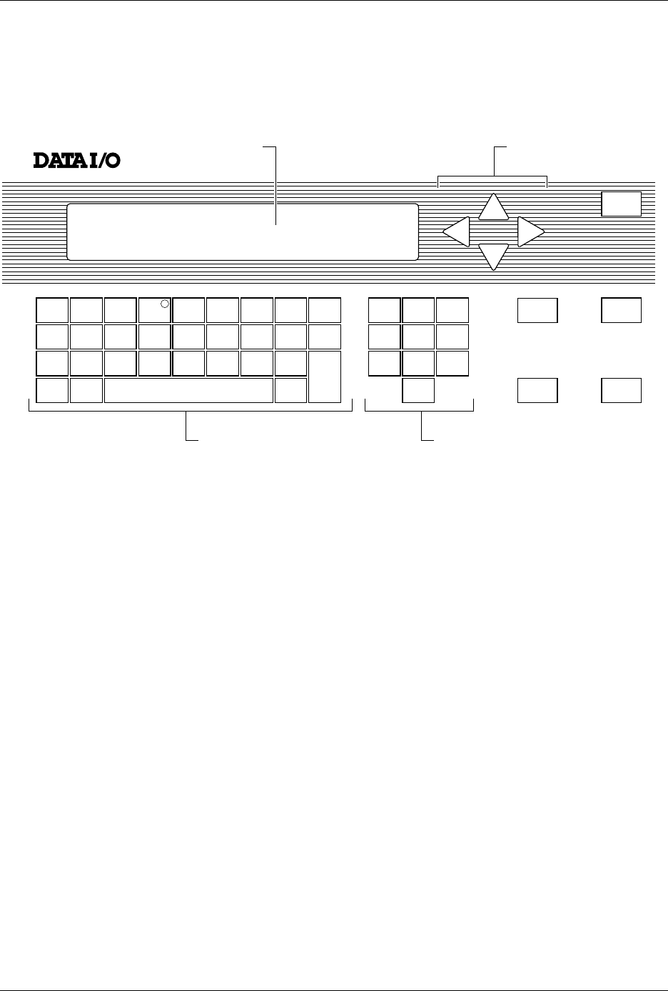
Front Panel
The primary features of the 2500’s front panel are described below (see
Figure 1-8).
Control Keys START
—Pressing
START
indicates that you are ready to begin the
operation you have selected.
STOP
—Pressing
STOP
once suspends system operation so you can
make an adjustment. Refer to the STOP commands described in the
Appendix B. Pressing
STOP
twice releases the programming module
clamp.
RESET
—Pressing
RESET
while in local mode stops the operation being
performed and returns you to the Main Menu (except in the Diagnostics
EEPROM test when pressing
RESET
returns you to the Diagnostics
Menu). After you press
RESET
, all counters are reset, and the 2500 is
ready to begin another operation.
CAL
—Pressing
CAL
calibrates labels to determine their reference
position on the label liner. This reference point is required for correct
label printing and application to the device.
Figure 1-8
The ProMaster 2500 Front Panel
!
_
$
"
*
,
#
:
;
=
<
%
~
>
&
@
?
'
\
.
(
+
/
)
-
c
1765-1
SHIFT
A
J
S
B
K
T
DEL
C
L
U
D
M
V
E
N
W
SPACE
F
O
X
G
P
Y
H
Q
Z
LOWER
CASE
I
R
ENTER
1
4
7
2
5
8
0
3
6
9
STOP
START
ON
DISPLAY ARROW KEYS
KEYBOARD NUMERIC KEYS
RESET
CAL

Introduction
1-12 3/97 ProMaster 2500 User Manual
Display
The 160-character, 4-line, back-lit display prompts you with menus
during setup and diagnostic testing and for all operations in local mode.
ON
—A green LED behind this status indicator is on whenever the
system is turned on. This is not a control key.
Main Menu
—The 2500 Main Menu is shown below.
Making a Selection
—To make a selection from a menu, enter the
number of the function you want to use. That function’s sub-menu will be
displayed.
Default Values
—On most of the front panel messages, the 2500 displays
the default value in parentheses. If you press
ENTER
without making a
change, the default value is entered.
Prompts
—To respond to a prompt, type the appropriate entry from the
keyboard. To answer Yes, press
Y
.
Keyboard
From the keyboard you can enter upper- and lower-case letters as well as
special characters. These are selected by pressing
SHIFT
and the
character key at the same time.
All keys except
ENTER
are auto-repeating, with a half-second delay.
The message
PRESS ANY KEY TO CONTINUE
does not apply to
SHIFT
or
LOWER CASE
. These keys are used most often to configure the 2500 to
operate in remote (
LOWER CASE
+
R
) and local (
LOWER CASE
+
L
)
modes.
Arrows
—Use the
↑
,
↓
,
←
, or
→
arrow keys to move the cursor.
* * * PROMASTER 2500 MAIN MENU * * *
ENTER THE NUMBER OF THE DESIRED FUNCTION
1 - OPERATIONS 3 - SYSTEM SETUP
2 - FILE UTILITIES 4 - DIAGNOSTICS

Introduction
ProMaster 2500 User Manual 3/97 1-13
TaskLink Software
TaskLink software runs on a PC and coordinates device programming,
testing, handling, labeling, and binning operations on the ProMaster
2500. TaskLink is available in a DOS version and a Windows™ version.
The software procedures and instructions in this manual assume the use
of TaskLink for DOS. If you are using the Windows version, refer to the
TaskLink for Windows Getting Started Guide
and the associated online Help
for detailed information.
PC System
Requirements
TaskLink (DOS) has the following minimum system requirements:
AT
,
PS/2
,
386
,
486
, or
Pentium™ PC
with the following:
• DOS 3.3 or later (DOS 5.0 or higher recommended)
• 640K RAM (2 MB of extended RAM recommended)
• Extended memory manager such as
himem.sys
or QEMM
(recommended)
• Disk-caching software, such as
smartdrv.sys
(recommended)
• Two RS-232C serial ports assigned as COM1 and COM2
•Microsoft
®
-compatible bus mouse (optional)
• A hard disk with at least 2 MB of free disk space
• Color monitor (recommended)
• 3.5-inch disk drive
• Two RS-232 serial cables
Modes of Operation
TaskLink displays different screens depending on whether it is to be run
by the system administrator or the system operator. These two modes are
started using different commands and serve different purposes.
•The
system administrator
defines the specific configurations for each
Task (job) that the operator will run. The menus in
administrator
mode
display all the options available through TaskLink. Specific
steps involved in creating a Task are described in Chapter 3.
•The
system operator
is interested in achieving quick, error-free
processing of devices. The first screen displayed in
operator mode
presents a list of Tasks that have been created by the system
administrator. The operator selects a Task to run and begins
processing devices after a minimal number of screen selections. The
typical procedure for selecting and running a Task is described in
Chapter 4.