2500_Users_Manual - 第340页
Trans lati on For mat s D-10 ProMaste r 2500 User Ma nual Formatted Binary Format, Code 10 Data transfer in the Formatted Binary format con sists of a stream of 8-bit data bytes preceded by a byte count and followed by a…

Translation Formats
ProMaster 2500 User Manual D-9
The 5-Level BNPF Format, Codes 08 or 09
Except for the start and end codes, the same character set and
specifications are used for the ASCII-BNPF and 5-level BNPF formats.
Data for input to the programmer are punched on 5-hole Telex paper
tapes to be read by any paper tape reader that has an adjustable tape
guide. The reader reads the tape as it would an 8-level tape, recording the
5 holes that are on the tape as 5 bits of data. The 3 most significant bits are
recorded as if they were holes on an 8-level tape. Tape generated from a
telex machine using this format can be input directly to a serial paper
tape reader interfaced to the programmer. the programmer’s software
converts the resulting 8-bit codes into valid data for entry in RAM.
The start code for the format is a left parenthesis, (Figs K on a telex
machine), and the end code is a right parenthesis, (Figs L on a telex
machine). The 5-level BNPF format does not have addresses.
Note: Data without a start or end code may be input to or output from the
programmer by use of the alternate data translation format code, 09. This
format accepts an abort character (10 hex) to abort the transmission.
Translation Formats
D-10 ProMaster 2500 User Manual
Formatted Binary Format, Code 10
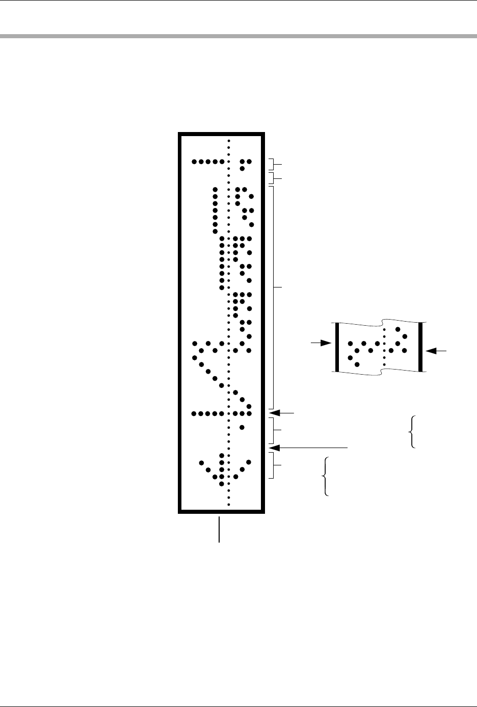
Data transfer in the Formatted Binary format consists of a stream of 8-bit
data bytes preceded by a byte count and followed by a sumcheck, as
shown in Figure D-3. The Formatted Binary format does not have
addresses.
The programmer stores incoming binary data upon receipt of the start
character. Data are stored in RAM starting at the first RAM address
specified by the Memory Begin Address parameter and ending at the last
incoming data byte.
Figure D-3
An Example of Formatted Binary
Format
2 BYTE HEX SUMCHECK (02FB)
2 NULLS
BINARY DATA
BIT
8
BIT
1
RUBOUT (START CODE)
4 NIBBLE HEX BYTE COUNT
1 NULL
ARROW
HEAD
08
49
2A
1C
08
0
2
0
0
0020 HEX
(32 DECIMAL)
HIGH
ORDER
LOW
ORDER
0075-2
Translation Formats
ProMaster 2500 User Manual D-11
A paper tape generated by a programmer contains a 5-byte, arrow-
shaped header followed by a null and a 4-nibble byte count. The start
code, an 8-bit rubout, follows the byte count. The end of data is signaled
by two nulls and a 2-byte sumcheck of the data field. Refer to Figure D-4.
If the data output has a byte count GREATER than or equal to 64K, an
alternate arrow-shaped header is used. This alternate header (shown
below) is followed by an 8-nibble byte count, sandwiched between a null
and a rubout. The byte count shown here is 40000H (256K decimal). If the
byte count is LESS than 64K, the regular arrowhead is used instead. Data
that are input using Formatted Binary format will accept either version of
this format.
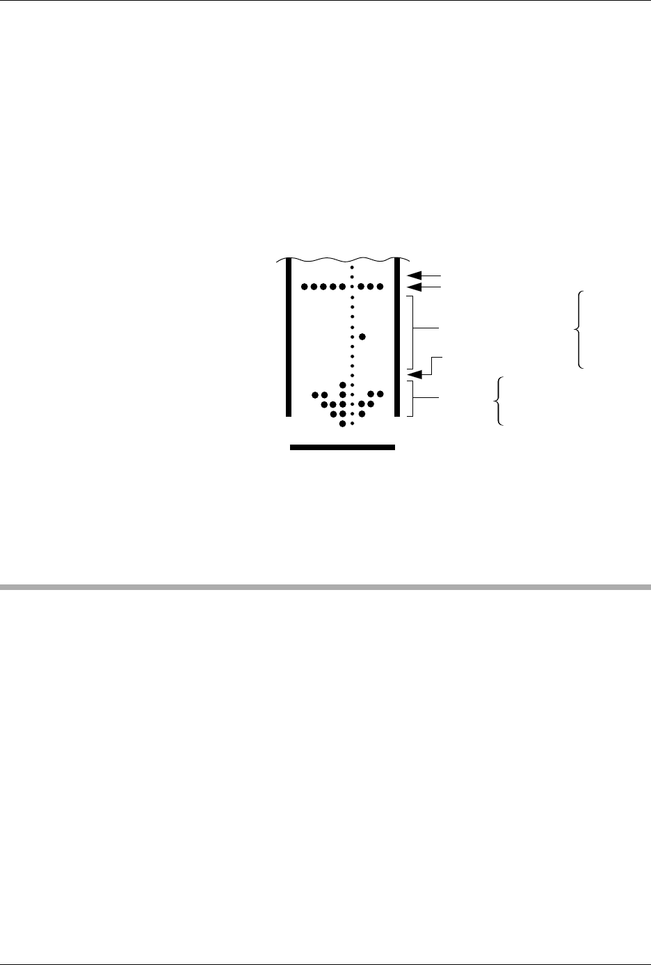
In addition, a third variation of this binary format is accepted on
download. This variation does not have an arrowhead and is accepted
only on input. The rubout begins the format and is immediately followed
by the data. There is no byte count or sumcheck.
DEC Binary Format, Code 11
Data transmission in the DEC Binary format is a stream of 8-bit data
words with no control characters except the start code. The start code is
one null preceded by at least one rubout. The DEC Binary format does
not have addresses.
Figure D-4
An Example of Formatted Binary
Format
RUBOUT (FF)
8 NIBBLE BYTE COUNT
NULL (00)
ARROW
HEAD
08
6B
3E
1C
08
0483-2
DATA
00
00
00
00
04
00
00
00