2500_Users_Manual - 第38页
Introduc tion 1-16 3/97 ProMast er 25 00 Use r Man ual The table below summ arizes the key s common ly used wi th TaskL ink and the function they serve. Note: Press the ESC key at any time to exit any menu or dialog b ox…
Introduction
ProMaster 2500 User Manual 3/97 1-15
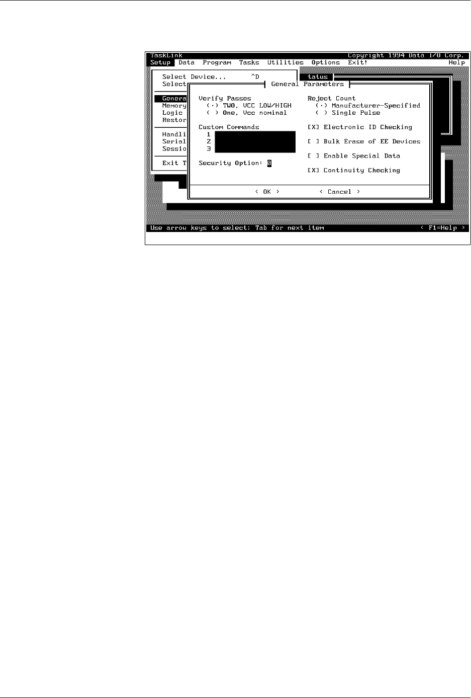
Push Buttons
—Dialog boxes contain one or more push buttons. To select
a push button, highlight it and press
↵
, or select it using a mouse.
<OK>
and
<Cancel>
are examples of push buttons.
Check Boxes [ X ]
—Check boxes toggle an option on and off. Use the
S
PACE
bar, or click on the check box with your mouse to toggle a selection
on and off.
Electronic ID
is an example of a check box.
Radio Buttons
(
•
)—Radio buttons are used to select an option from a
list of mutually exclusive options. Use the arrow keys or click on the
option to select a radio button option. The two options listed under
Verify Passes
are examples of radio buttons; selecting one deselects the
other.
Parameter Entry Fields
—These fields allow you to input information
that TaskLink needs. When highlighted, text entered at the keyboard goes
into the entry field.
Custom commands
is an example of a parameter
entry field.
Online Help
For more detailed information on any aspect of TaskLink, context-
sensitive online help documentation is available by:
• Clicking the mouse button on the
< F1 = Help >
push button at the
bottom right of the screen.
• Moving the cursor to a selection and pressing
F1
.
All topics covered in online documentation are also accessible from the
General Help Index
in the
Help
menu.
TaskLink Screen
Movement Summary
Both the mouse and the PC keyboard can be used to select items from the
TaskLink menus. All screen movement and selection instructions in this
manual are given using the PC keyboard commands. If you are using a
mouse, simply point the mouse to an item on TaskLink’s action bar,
boxes, or buttons, and select the item by clicking the mouse button.
Figure 1-10
TaskLink General Parameters
Dialog Box

Introduction
1-16 3/97 ProMaster 2500 User Manual
The table below summarizes the keys commonly used with TaskLink and
the function they serve.
Note: Press the ESC key at any time to exit any menu or dialog box without
saving and to display an Exit TaskLink confirmation window.
User Interface Options TaskLink Screen
—System operators will use TaskLink for most of their
communication with the system. Most operator prompts are displayed in
the TaskLink screens on the PC monitor.
Front Panel
—The 2500’s keyboard and display will be used by the
system operator on limited occasions to:
• Adjust specific handler parameters using special function key
commands (refer to Appendix B for Firmware key commands).
• Align the beam to the programming module.
• Read device handling messages.
PC Key(s) Description of Action
T
AB
Moves the cursor to the
next field
(forward) in a dialog
box.
S
HIFT
+
T
AB
Moves the cursor to the
previous field
(backward) in a
dialog box.
↵
Accepts
the current
selections
in a dialog box. In a
multiple-line text entry field, this key moves the cursor
to the next line or the beginning of the next field.
E
SC
Cancels
a dialog box
without saving
any changes, or it
cancels any operation in progress.
Arrows
Moves the cursor between selections in a dialog box.
H
OME
, E
ND
Moves the cursor to the
beginning
or
end
of a list.
P
G
U
P
,
P
G
D
N
Moves the cursor
up one screen
or down one screen.
F1
Accesses context-sensitive
help
.
F2 Accesses lists
from several dialog box entry fields. You
are prompted to press this key at appropriate times by
the TaskLink message line in the lower left corner of the
screen.
C
TRL
+
F1
Checks communication between TaskLink and the
Programmer port
on the 2500 (enter command from
TaskLink’s main screen).
C
TRL
+
F2
Checks communication between TaskLink and the
Remote port
on the 2500 (enter command from
TaskLink’s main screen).

Introduction
ProMaster 2500 User Manual 3/97 1-17
The 2500’s keyboard and display will be used by the system
administrator and/or service technician when they want to:
• Stop the handler during a job (Task), adjust a parameter, and then
continue running the Task from the same point. (A complete list of
the available
STOP
commands can be found in Appendix B.)
• Run tests on the labeler using the
Print Only
mode.
•Operate in
Local
mode to run system diagnostics.
2500 Handler Specifications
Functional
Print Density
12 to 26 characters per inch (dot matrix labeler)
11 to 28 characters per inch (thermal labeler)
Control Interface
Three serial RS-232C ports (default: 9600 Baud)
Throughput
Up to 550 devices per hour
(actual throughput depends on programming/testing time for the
specific device and labeling requirements)
User RAM
8MB standard
Floppy Disk Format
Double-sided, quad-density 3.5” disk with 135 tracks/inch; 1.44MB
formatted
Mass Storage Module
Internal hard drive (user drives C and D; system drives H and I);
User drives formatted to 32MB, maximum number of files per drive
= 512.
Controller
Motorola 68000 16-bit microprocessor
Communication Standard
RS-232C
Data transfer rate
300 to 19.2K baud (data file transfer up to 115.2K baud using
TaskLink)
Programming Modules DIP:
8- to 28-pin in 0.3-inch package width
20- to 32-pin in 0.6-inch package width
PLCC:
20-, 28-, 32-, 44-, 52-, 68-, and 84-pin
Lead Pitch Width: 0.050 inch
SOIC:
Package Width
0.150 (150 to 220 mil)
0.300 (300 mil)
0.350 (0.330 to 0.350)
0.450 (0.420 to 0.450)
0.530
*
(0.500 to0.530)
* To use a 500-mil SOIC programming module, you must have the 88-pin version of the
ProMaster 2500.
Max. Pin Count
8 pins
32 pins
32 pins
40 pins
56 pins